Volume 7, No 4 - April, 2002
|
|
Volume 7, No 4 - April, 2002 |
|
|
|
|
|
|
President - |
Vice President - |
||
|
Treasurer - |
Secretary - |
Ed Gladkowski |
|
|
Webmaster - |
Editors - |
||
|
Founder - |
Membership Information
Membership is open to all those interested in machining metal and tinkering with machines. The purpose of the club is to provide a forum for the exchanging of ideas and information. This includes, to a large degree, education in the art of machine tools and practices. There is a severe shortage of written information that a beginning hobbyist can understand and use. This makes an organization such as this even more important.
Business Meeting
Minutes are sent via email or regular mail to club members.
Regular Meeting
|
|
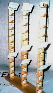
1:00 p.m., March 9, 2002 at Collier Library, 6200 Pinemont, Houston, Texas, President Dennis Cranston presiding. Jan Rowland built a name tag tree for member's badges. There were 40 attendees plus one visitor. |
Presentation
|
|
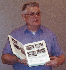
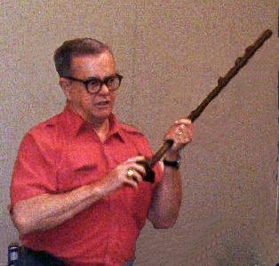
Tom Moore displayed a variety of books from his technical collection. |
Show and Tell
|
|
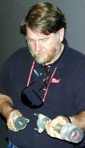
Vance Burns showed a commercial gas burner he bought. |
Don Foster showed two ball or radius turning attachments he built for his lathe. |
|
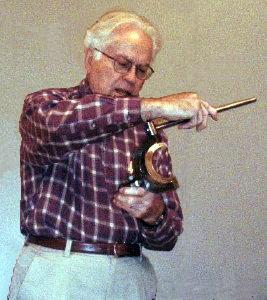
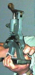
Joe Williams demonstrated his version of a welding positioner. |
Larry Hill (Mr. Sandman) showed a simple home made muller and his own brand of foundry oil sand he made using it. |
Ray Ethridge showed a very unusual two piece bronze flywheel casting. Very few members had seen a flywheel of that type before. |
Ed Gladkowski showed an unorthodox tool for turning smooth finishes on a worn lathe. |
|
|
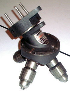
Joe Scott showed a quad drill press head and an example of the results of electro-lytic derusting. |
|
|
|
|
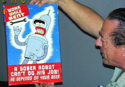
| Art Voltz displayed an amazing collection of steady rests, a shop sign along with very interesting and ingenious functional wooden mockups of a Lewis shaper vise and 10x24 Logan lathe steady rest he is developing. |
|
|
|
| Our swap meet was held in the Rutland Tool company parking lot on Saturday March 23. Later that same day Rutland auctioned off its scratch and dents and customer returns. Thanks to David Adamek, the auctioneer, and the rest of the Rutland gang. David Whittaker of HMSC was responsible for getting the event set up. |
|
Featured Article
Observations from a Programmer-Machinist - Part 1
by John Lilly - HMSC Member
This is the first of a series of articles that I hope will stimulate some interest and discussion among those members of the club interested in CNC (computer numerical control) machining.
As with all machines and machining operations, safety is the most important part of the job. All of the safety precautions used in standard machining also apply to CNC machining. This article discusses some, but not all, of the additional safety concerns with CNC machining.
For safety reasons always make at least one dry-run of a new or modified CNC program. The computer will do exactly what it thinks you as a programmer have instructed it to do. Few people go thorough life without having given an instruction that is not interpreted as expected. When a CNC machine does not do what is expected, the results can be damage to the tooling, the work piece, the machine, and even the operator. Tooling hitting something unexpectedly is known as a crash. A dry-run on a milling machine is a execution of the program made without the spindle turning and usually with the table lowered safely out of the way. On a lathe, the dry run is made without tooling, without the work piece or both. The new graphical software systems now available have helped a great deal in program verification. However, in my humble opinion they do not replace the need for a dry-run of the program.
First comes the program header, a verbal explanation of what the program is doing. This is followed by a short section of code used to clear out any modes left in the system by previous programs. This section should do the following:
The manufacturer's manuals for your machine and controller should be carefully studied. The manual is a good starting point, but, as with all software documentation, is prone to errors. Do not make the mistake of thinking that a command will work in a particular way on your machine. Not all machines respond the same way to even standard commands. Both coordinates, and data entry methods can be different from machine to machine. Even two identical machines with the same controllers and same software revision can respond differently if the setup file for the software is configured differently.
The next article will be about some of the very basic whats and whys of CNC machining.
Articles on Lathe Attachments
Lathe Cross Slide Measuring Device
by Dick Kostelnicek - HMSC Member
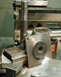
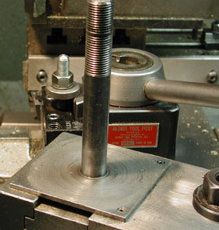
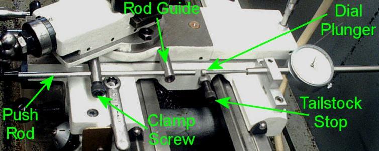
Here is what I use for a cross slide measuring device. Its a poor man's DRO (digital read-out). I appropriated the design concept from John Hoff, another HMSC member.
A bolt is used as a tailstock stop. It is threaded into one of the holes in the saddle that are normally used for attaching the follower rest. The bolt has a jam nut that sets its exposure just far enough out so that the tail stock casting (not seen) will not collide with nor damage the rod guides and dial plunger when it is pushed up against the saddle.
|
|
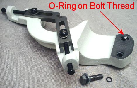
O-Ring Bolt Retainer by Dick Kostelnicek - HMSC Member |
Positioning and engaging the threads of the
two bolts that hold my follower rest onto the lathe's saddle, required
both dexterity and patience. Often, one of the bolts fell down
into the bed pan's mass of oil laden chips. That bolt had to
be first found and then cleaned before reuse. Also, these bolts were
good candidates for either getting lost during storage
or appropriated for some other application. The solution was to counterbore the rest's two mounting holes
1/16 in. deep to accommodate o-ring retainers stretched over the bolt threads
|
|
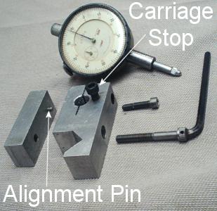
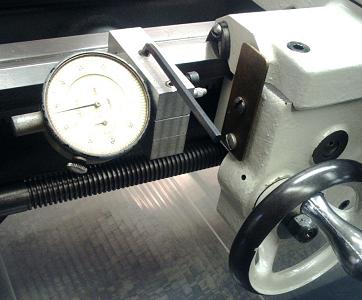
Lathe Indicator Holder by Dick Kostelnicek |
|
For measuring small movements of the lathe carriage near the headstock, I use a 0.5 in. travel dial indicator clamped to the lathe bed. The indicator is quite useful for determining when to disengage the half-nut and withdraw the cutter during a threading operation. The indicator holder is made from aluminum. It has a 3/8 in. hole, expansion slot, and an Allen head cap screw that cinches the dial indicator's slide barrel. The holder's lower clamp bar has an alignment pin that prevents the bar from rotating as the clamp screw is tightened around the lathe's V-way. The Allen head clamp screw has a L-wrench silver soldered to it. All that is necessary is a quarter turn of this screw to allow the holder to slide along the lathe bed. A carriage stop screw prevents displacement of the dial plunger past full scale.
Sometimes I need to measure carriage travel greater than 0.5 in. I have another holder to the right of the carriage with a 2 in. dial indicator with its plunger pointed toward the headstock. Fortunately, its dial has two concentric scales that provide readings for both left and right displacements
|
|
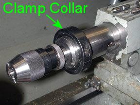
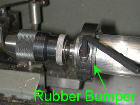
Tail Stock Clamp Collar by J. R. Williams - HMSC Member |
|
|
|
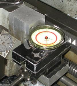
Trav-a-Dial Lathe Longitudinal Measuring Device by J. R. Williams - HMSC Member |
The unit is the mechanical equivalent of the new digital read-outs of today's market. I built an aluminum block bracket to mount the unit to the side of the apron of the lathe. The factory bracket (extra cost) mounted to the top of the apron and it was not suitable. The unit uses a small barrel shaped, lightly knurled, roller that rolls on the side of the way. The mount allows the unit to be tipped slightly to change the reading. I use a known length bar (micrometer standard of 10 to 12 inches) and move the carriage away from the locked down carriage stop. This solves the calibration problem. I did add a plastic cover to the dial to keep hot chips from damaging the original one. The secret of making a clear lens of this type is to add a few drops of clear machine oil to the surface between the two lens. The plastic cover is machined to snap over the factory lens. You can see the paint is rubbed off of the top due to my thumb rubbing the surface while turning the dial to the new Zero setting. It has 14 years of service and no problems other than an occasional calibration check. An old two inch dial indicator served me for some 6 years before I bought the unit.
|
|
Tool Post Spacer by J. R. Williams - HMSC Member |
|
|
The next meeting will be held on Saturday April 13, 2002 at the Collier Library 6200 Pinemont, Houston, TX at 1:00 p.m. Bring along a work in progress to show. Visit Our Web Site |
 |