Volume 10, No 4 - April 2005
|
|
Volume 10, No 4 - April 2005 |
|
|
|
|
|
| President - |
Vice President - |
||
| Treasurer - |
Secretary - |
||
| Webmaster |
Editors - |
||
| Founder - |
SIG Coordinators - |
Statement of Purpose
Membership is open to all those interested in machining metal and tinkering with machines. The club provides a forum for the exchanging of ideas and information. This includes, to a large degree, education in the art of machine tools and practices. Our web site endeavors to bring into the public domain written information that the hobbyist can understand and use. This makes an organization such as this even more important.
April Program
March Regular Meeting
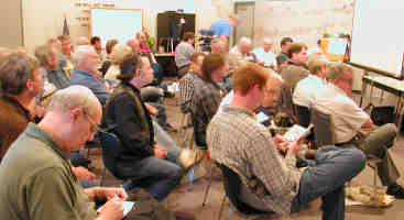
Business Meeting
Minutes are sent via email or regular mail to club members.
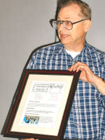
Presentation
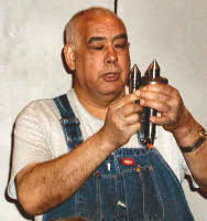
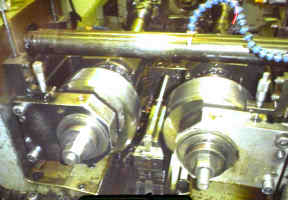
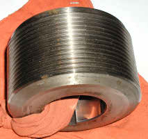
Cloice Duncan from Houston Grinding and Manufacturing
presented a program on commercial thread forming using rollers instead of cutters.
The company rolls threads on compressor rods in excess of 15 feet in length
and 8 inches in diameter.
Show and Tell
|
|
|
Novice Sig
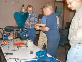 The
novices explored three mechanical drill bit sharpeners. They are General Tool
no. 825, Black & Decker no. 7980, and Drill Doctor no. 400. The General
Tool fixture uses an ordinary grinding wheel and must be sharpened slowly to
avoid drawing the drill temper. The Black & Decker machine has its
own grinding wheel but must be used slowly to avoid drill over-heating. The
Drill Doctor uses a diamond wheel that does not seem to over-heat the drills.
Dick Kostelnicek demonstrated the drill doctor; this machine costs about $100.
Several club members discussed the merits of each sharpening method and they
suggested improvements such as using a white grinding wheel suited for side
grinding.
The
novices explored three mechanical drill bit sharpeners. They are General Tool
no. 825, Black & Decker no. 7980, and Drill Doctor no. 400. The General
Tool fixture uses an ordinary grinding wheel and must be sharpened slowly to
avoid drawing the drill temper. The Black & Decker machine has its
own grinding wheel but must be used slowly to avoid drill over-heating. The
Drill Doctor uses a diamond wheel that does not seem to over-heat the drills.
Dick Kostelnicek demonstrated the drill doctor; this machine costs about $100.
Several club members discussed the merits of each sharpening method and they
suggested improvements such as using a white grinding wheel suited for side
grinding.
One Machine Tool Practices notebook was given to a new novice.
Next time we will sharpen drills by hand. The experienced club members will be asked to demonstrate their techniques. Club members are asked to bring in identified drills that need sharpening. by Rich Pichler
Casting Sig

Featured Articles
A Bit About Lathe Bits
by
Dick Kostelnicek - HMSC Member
 There
are two important angles on a lathe cutter bit: the top rake and the
front clearance. Refer to the diagrams at the left for their locations. Yes,
there are several other important angles, but I want to concentrate on
the two mentioned and their relationship to the lathe's center line. We all have
learned the bit's cutting edge should be on center,
as illustrated in the top-left drawing, but what if
it isn't? What are the consequences?
There
are two important angles on a lathe cutter bit: the top rake and the
front clearance. Refer to the diagrams at the left for their locations. Yes,
there are several other important angles, but I want to concentrate on
the two mentioned and their relationship to the lathe's center line. We all have
learned the bit's cutting edge should be on center,
as illustrated in the top-left drawing, but what if
it isn't? What are the consequences?
The top diagram shows a lathe bit on center with a top rake of 16 degrees and a front clearance of 8 degrees. These are the commonly recommended angles for low carbon steel. The pointed wedge formed by the top rake and front clearance surfaces is responsible for the shearing or slicing away metal from the rotating work. The back sloping rake pulls away the cut material or chip from the work. After a cut is initially started by the sharp tip of the bit, the tip is no longer involved in the actual cutting (except in the lightest of cuts). Chips are torn away from the work by the wedging action of the rake and front clearance surfaces rearward of bit's sharp point. This is much like a pen knife cutting wood along the grain. The sharp knife edge is responsible for initially slicing into the wood, but as the cut progresses the thicker portion of the blade behind the tip will pry the wood apart without the edge coming in contact with the wood. However, if the edge of a lathe bit were as slender as that of a knife, it would break off due to the extreme downward crushing pressure caused by the rotating work. Some bits, namely those made from cemented carbide, have zero and some times negative top rake. Although cemented carbides are quite hard, they are weak in shear and especially in tension. Such bits need all the support they can get, and hence, are never formed into low angle cutting wedges.
The front clearance is necessary so the bit can poke into the work . In other words the bit's edge needs to get under the chip to separate it from the rotating stock. The larger the front clearance becomes, the less interference there is in carving out the chip. As the front clearance increases so does the instability of the cutting action. Think of the front clearance facet as a shoe resting against the work. It stabilized or regulates the bit from being pulled into the work. Once pulled in it will eventually spring back. This will cause a chattering effect especially if the lathe and work are mechanically resonant at that frequency. Another negative in having too much front clearance is the lack of upward support for the tip of the bit against the forces thrust against it by the rotating work piece during the cutting action.
What are the consequences of not putting the bit on center? Look at the middle picture. The diameter of the work is 1/2 inch, and the bit is set 0.020 inches above center. Removal of the chip occurs along a line tangent or perpendicular to the work's radius line passing through the point where the bit contacts the work. The angle between this radius and bit's top facet or top rake angle has been increased from 16 to 21 degrees. The front clearance has been reduced from 8 to 3 degrees. Here the tool may not dig into the work. If you find that advancing the tool into the work does not remove the required amount of stock, there may not be enough front clearance
The bottom diagram illustrates what happens when the bit is set 0.020 in. below the centerline. The effective top rake is reduced from 16 to 11 degrees, while the front clearance is increased from 8 to 13 degrees. If you remove more stock than the amount of infeed on a heavy cut or if the tool bit chatters, you may have too much front clearance.
In summary, the top rake and front clearance angles change by the same amount but in opposite directions. Above center, the top rake increases while the front clearance decreases. The opposite happens when the bit's cutting edge is below center. Roughly speaking, the angular change in degrees is given by the formula A = 115 S / D; where A is the angular change, S is the off-center distance, and D is the work diameter.
Drill Grinder
Modification
by J. R. Williams
- HMSC Membe
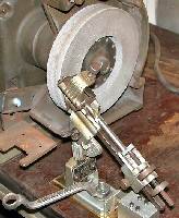
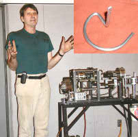
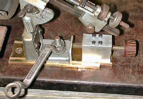 The
photos show modifications I made to my old Craftsman Drill Grinding fixture
(Cat. No 9-6677). Normal operation requires the
operator to advance the drill into the wheel by using the two knurled round nuts. When the drill is advanced in this manner, the drill
rotates as it is in contact with the fixture's locating finger. My
modification advances the drill by loosening the clamp nut with the offset
wrench and then moving the whole fixture to the wheel. Very
easy to use.
The
photos show modifications I made to my old Craftsman Drill Grinding fixture
(Cat. No 9-6677). Normal operation requires the
operator to advance the drill into the wheel by using the two knurled round nuts. When the drill is advanced in this manner, the drill
rotates as it is in contact with the fixture's locating finger. My
modification advances the drill by loosening the clamp nut with the offset
wrench and then moving the whole fixture to the wheel. Very
easy to use.
The base plate is made from a section of 1/4" thick brass with a parallel section for the guide 1-1/4" wide and 1/16" deep. It is secured to the bench top with two flat head wood screws. The base of the Craftsman fixture has been machined to fit the brass base. This allows the unit to slide freely for adjustment. The unit is clamped in place with the vertical 3/8" stud and nut. The end of the fixture was milled with a flat. The 1/8" flat plate was secured to the base with three No. 6-32 flat head machine screws. The screw to advance the unit is a 4" long section of 5/16" threaded brass rod with an old plastic knob. The support block is a 1" x 1-1/4" x 1-3/4" aluminum threaded for the 5/16" rod and secured to the brass base with four No.6-32 socket head cap screws.
The grinding wheel is 1" wide x 6" diameter with a depressed center and is designed for this purpose. It has been used to grind drills for the past 30 or so years in my shop. (No idea where or how the deep groove was made in the outer surface).
The
flange for the wheel has a series of 10-32 tapped holes for short socket
head cap screws to be used for balancing purposes. I had an imported
wheel that required considerable work to get it balanced. I tried this method for a while and finally
tossed the wheel.
Using a Tool-Maker's
Ball
by Steve Clay - HMSC Member
 An
uncommon, but not unheard of, problem is that of setting precise hole locations
on surfaces that intersect at arbitrary angles (see the drawing at the right).
A time honored technique for locating such holes employs a tool-makers
ball. Being not new to this sort of work, I thought that they still were a common
article. But, a Google search turned
up nothing. However, at the MSC web
site, I found part no.
64254899. So, they are not yet extinct. Typical ball dimensions are specified
to a ten-thousand of an inch. For the MSC ball: D = 0.5000, H = 0.3125,
and S = 0.2500.
An
uncommon, but not unheard of, problem is that of setting precise hole locations
on surfaces that intersect at arbitrary angles (see the drawing at the right).
A time honored technique for locating such holes employs a tool-makers
ball. Being not new to this sort of work, I thought that they still were a common
article. But, a Google search turned
up nothing. However, at the MSC web
site, I found part no.
64254899. So, they are not yet extinct. Typical ball dimensions are specified
to a ten-thousand of an inch. For the MSC ball: D = 0.5000, H = 0.3125,
and S = 0.2500.
Consider the setup on a vertical mill of the Bridgeport type as shown in the drawing at the right. Suppose we wish to put a hole in the inclined surface relative to a preexisting reference hole that is located on the flat surface. Specified are the height "X" of the hole axis crossing above the flat surface and the angle "Y" for the inclined surface.
What follows is a procedure using a tool-makers ball to accomplish the task at hand:
|
Visit Our Home Page at |
 |
Right
click below then select [Save Target As..]
From Netscape select [Save Link As..]
Microsoft
Word version of this newsletter 221 KB