Volume 9, No 8 - August 2004
|
|
Volume 9, No 8 - August 2004 |
|
|
|
|
|
| President - |
Vice President - |
||
| Treasurer - |
Secretary - |
||
| Webmaster |
Editors - |
||
| Founder - |
SIG Coordinators - |
Statement of Purpose
Membership is open to all those interested in machining metal and tinkering with machines. The club provides a forum for the exchanging of ideas and information. This includes, to a large degree, education in the art of machine tools and practices. Our web site endeavors to bring into the public domain written information that the hobbyist can understand and use. This makes an organization such as this even more important.Coming August Presentation
Don Foster will present the method that he used in the past to obtain patents on ideas he has created. He said the presentation should be fairly short.
Regular Meeting
 Collier Library, Houston Texas, 1:00 p.m., July
10, 2004, Chuck West, President presiding. 38 members were present with
4 guests. George Cunningham, DiAne Landgren, Joe Yeiser, and John
Hoffer.
Collier Library, Houston Texas, 1:00 p.m., July
10, 2004, Chuck West, President presiding. 38 members were present with
4 guests. George Cunningham, DiAne Landgren, Joe Yeiser, and John
Hoffer.
Tom Moore announced a swap meet for July, 24 starting at 9:00 a.m. at Zube
Park. Go north on Roberts Rd., past the creek, and turn right into
the HALS work area.
Business Meeting
Minutes are sent via email or regular mail to club members.
Presentation
|
|
|
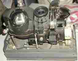
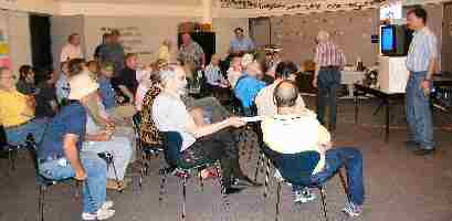
George
Cunningham, retired professor of structural design at Rice University, showed
a Norden Bombsight (left photo) that he purchased after WW II and is now
donating to an Industrial Archeology Museum run by our club President, Chuck
West. He also showed some artifacts from both world wars, including a map of
Germany printed on silk for use by soldiers behind enemy lines. Professor Cunningham was
driven to the meeting by DiAne Landgren (visitor).
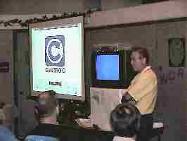
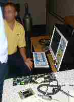 Terry
Ruppe of Arrow Controls talked about CNC control kits for OEM and Retrofit.
Terry explained how multiple tools heights and diameters can be automatically
sensed, calibrated, and remembered by a CNC machine tool run with Centroid
Control Systems hardware and software.
Terry
Ruppe of Arrow Controls talked about CNC control kits for OEM and Retrofit.
Terry explained how multiple tools heights and diameters can be automatically
sensed, calibrated, and remembered by a CNC machine tool run with Centroid
Control Systems hardware and software.
This is the control system that Doug Chartier chose for the retrofit of his
BOSS 9 Bridgeport mill.
Special Interest Groups Activity
 Novice
Group
Novice
Group
The use of various types of knurling tools was demonstrated. Finished knurled examples were shown. A fool proof knurling method, using tables of the correct work diameter was distributed. This diameter allows the knurl's teeth to exactly overlay impressions from previous rotations of the work.
Rich Pichler showed a video tape making a swivel foot for a 6 in. C-clamp.
Only one novice notebook on machining was available for distribution. The other two novices were invited to come back next time for their notebooks. Next meeting we will explore Rich Pichler's minimum machinist tool box, and, time permitting, we will lay out a drill gauge.
Foundary Group
On Sunday, July 18, members of the foundry SIG met at Zube park. Those present were Dennis Cranston, Emmett Carstens, Ray Ethridge, Doug Baugher, Ed Gladkouski and Tom Moore. We fired the two club furnaces for the first time. The smaller furnace was used for two pours. The large furnace fired OK, but will need some alterations before we can use it regularly. Using molds of Petrobond, we cast 8 aluminum railroad switch frogs without a problem.Tail Gate Swap Meet
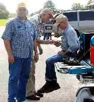
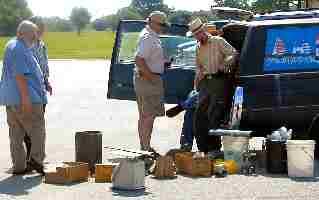 The
annual tail gate swap meet was held at Zube Park, north of Houston, TX on July
24. 2004.
The
annual tail gate swap meet was held at Zube Park, north of Houston, TX on July
24. 2004.
Show and Tell
|
|
|
|
|
|
|
|
Joe Williams (not pictured) passed around a can full of of take what you want tools.
Featured Articles
Jib Crane
for My Mill
by J. R. Williams
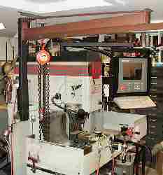
 I have revised my ceiling mounted beam to be a
formal Jib Crane after a Uni-Strut that I had been using came down in
a recent shop fire. The unit is mounted on a steel plate attached to
the side of the mill using a lifting hole thru the base section with a
large bolt (1-1/4 in.) and two 1/2 in. bolts at the top. The unit has large
double row ball bearings for the pivots with the pivot pins turned down
from 1-1/4 in. B7 Cap Bolts to fit the bearings (25 mm bore). The
horizontal beam is a section of 1/4 x 2 x 3 in. rectangular tube with a
section of Uni-Strut for the trolley attached with a number of
button head cap screws. The vertical member is 1/4 x 2 x 4 in.
rectangular tube. The trolley has ball bearing wheels with steel
wheels pressed on the outside and has a small flange to secure the
trolley from moving sideways.
I have revised my ceiling mounted beam to be a
formal Jib Crane after a Uni-Strut that I had been using came down in
a recent shop fire. The unit is mounted on a steel plate attached to
the side of the mill using a lifting hole thru the base section with a
large bolt (1-1/4 in.) and two 1/2 in. bolts at the top. The unit has large
double row ball bearings for the pivots with the pivot pins turned down
from 1-1/4 in. B7 Cap Bolts to fit the bearings (25 mm bore). The
horizontal beam is a section of 1/4 x 2 x 3 in. rectangular tube with a
section of Uni-Strut for the trolley attached with a number of
button head cap screws. The vertical member is 1/4 x 2 x 4 in.
rectangular tube. The trolley has ball bearing wheels with steel
wheels pressed on the outside and has a small flange to secure the
trolley from moving sideways.
I needed the unit to lift the 6 in. Kurt chuck, my old B&S dividing head,
or a 8 in. rotary table to the mill's table. The side shields on the
table make lifting anything to the table difficult. (This old man
cannot handle such loads easily.) The dividing head is around 80 pounds.
Disassembling a 3-Jaw
Scroll Chuck
by Dick Kostelnicek - HMSC Member
Have you turned a work piece that was so large that some chips got into the 3-jaw chuck's gearing? This often happens when over extended jaws uncovered the scroll gear. Using compressed air to clear the scroll of chips will often send debris deep into its inner workings. Inside the chuck, dirt and chips can inhibit the movement between the scroll gear and a jaw's rack, often making it impossible to move the jaws without damaging the chuck. When this happens, immediately disassemble and clean the chuck. Forcing or blowing compressed air into the scroll gear will seldom resolve the problem and may accentuate it.
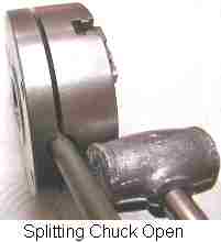
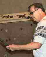
 First,
remove all the screws from the chuck's back plate. Place the chuck key in the square
hole of the pinion gear on the side of the chuck. Gently tap the key with a soft faced (lead) hammer as shown in
the left hand photo. The back plate will begin to separate from the front body
of the chuck.
Now, use two screwdrivers, one diametrically opposite the other, and gently pry
the two chuck halves apart. The pinion gear, that is driven by the chuck key, will fall
free from the split halves.
First,
remove all the screws from the chuck's back plate. Place the chuck key in the square
hole of the pinion gear on the side of the chuck. Gently tap the key with a soft faced (lead) hammer as shown in
the left hand photo. The back plate will begin to separate from the front body
of the chuck.
Now, use two screwdrivers, one diametrically opposite the other, and gently pry
the two chuck halves apart. The pinion gear, that is driven by the chuck key, will fall
free from the split halves.
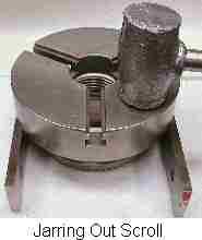
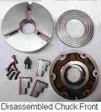
Place the front half of the chuck on two parallels as shown in the photo at the right. Place a soft cushion under the chuck and tap all around the chuck's top surface with a soft faced hammer. The scroll gear should fall out, downward, and free from the chuck body. Now remove the three jaws by sliding them outward by hand.
That's all there is to it. Clean all parts in a mineral solvent. Check for any dings, or upset metal on all parts. Remove the dings with a file or rubbing stone. Ensure mating surfaces will not bind. Apply a light coat of #10W oil to all parts and reassemble.
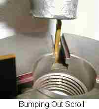
 Now,
if the scroll didn't drop free under its own weight from the gentle
tapping, then try bumping the scroll out using a soft rectangular
brass bar as seen in the left photo. This assumes that the jaws were removed
prior to disassembly or that the scroll has dropped just enough to disengage the
jaw's rack
and allow them to slide free. Bump the scroll gear through each of
the three jaw openings in turn. You don't want to wedge the scroll by tapping
in one place too much. Flip the chuck body over and see which side of the scroll
gear needs to be bumped next. In the worst case, possibly due to internal rusting,
use 3 wide rectangular brass bars of equal length. Invert the chuck so that it
is supported by the 3 bars that are pressing against the scroll gear. The assembly
should be mounted in an arbor press. Press down on the portion
of the chuck body that is inside the large hole in the scroll gear. If this doesn't separate the
scroll from the chuck, get a bigger hammer or call on an expert!
Now,
if the scroll didn't drop free under its own weight from the gentle
tapping, then try bumping the scroll out using a soft rectangular
brass bar as seen in the left photo. This assumes that the jaws were removed
prior to disassembly or that the scroll has dropped just enough to disengage the
jaw's rack
and allow them to slide free. Bump the scroll gear through each of
the three jaw openings in turn. You don't want to wedge the scroll by tapping
in one place too much. Flip the chuck body over and see which side of the scroll
gear needs to be bumped next. In the worst case, possibly due to internal rusting,
use 3 wide rectangular brass bars of equal length. Invert the chuck so that it
is supported by the 3 bars that are pressing against the scroll gear. The assembly
should be mounted in an arbor press. Press down on the portion
of the chuck body that is inside the large hole in the scroll gear. If this doesn't separate the
scroll from the chuck, get a bigger hammer or call on an expert!
Truing Those Tired Old Chuck
Jaws
by
Dick Kostelnicek - HMSC Member
 Does your
3-jaw scroll chuck have any of the following ailments?
Does your
3-jaw scroll chuck have any of the following ailments?
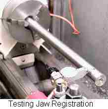
(A) It no longer centers a perfectly round test bar giving a runout of 3/1000 in.or more.
(B) Runout or registration near the jaws is much different than it is six inches out from the chuck (see left photo).
(C) You�re unable to re-chuck a work piece to the same accuracy even though you witnessed the work to the numbered jaws.
If you said YES, then read on, for it is time to re-true those tired old jaws. But first, disassemble, clean, and reassemble the chuck as described in a companion article in this newsletter.
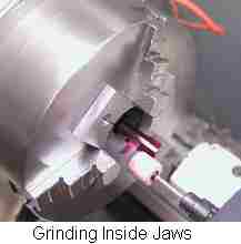
Truing the internal jaws on a 3-jaw scroll chuck is accomplished by grinding the jaw's end facets ( the narrow flat face that touches the work ) parallel to the lathe's axis. Since you will be grinding the hardened facets in the lathe ( photo upper right ), they will end up with a curved rather than flat facet. This is not a problem if the internal grind diameter is at least as large as the maximum diameter bar you will chuck ( I use a diameter slightly less than the chuck's pass through hole opening as the grind diameter ).
Next, the jaws must be pushed outward with a force comparable to that normally used in chucking work. If this is not done, the loose meshing or backlash between the scroll gear and the jaw's rack will not be taken up, resulting in a non concentric grind of the jaw facets. The photo shows the grinding operation using a 1/2 in. dia. stone wheel mounted in a 5/8 in. dia. pencil air die grinder. The die grinder is held in a 5/8 in. boring bar tool holder mounted on the lathe's cross slide. Prior to grinding, paint the facets with red layout die and protect the lathe's ways with a moist shop towel. The complete removal of the red die from all facets will indicate that you are done grinding. Run the carriage, under power longitudinal feed, back and forth as slowly as possible. The stone should completely pass beyond the facets both front and back. This ensures that any taper of the stone will not taper the jaws. The lathe rotational speed should be as slow as possible. Take off about 1/1000 or less per pass until all facets are bright throughout their length. If you attempt to take deeper cuts, the stone will skip due to its lightness of mass and produce an irregular grind. Then pass the stone back and forth without changing the cross slide setting till the grinding stone 'sparks out'.
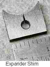
 Now just
how do you maintain outward pressure on the jaws while grinding ? Make
a set of three expander shims like the one seen in the left hand photo. The material is
1/8 in. steel plate. The three shims were band sawed from a single
plate that had a large hole bored in it to the size of the chuck's
pass through opening. The small hole and the sawed slit provides the shim
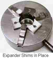
with a spring effect. When the three expander shims are seated against the sloped
sides of the jaws ( see photo at right ) and the scroll
is tightened, the scroll-to-rack backlash is taken up. Prior to tightening,
adjust the width of the shims with a belt sander so that there is
little play between each shim and the jaws. You might want to number the shims such
as '2 - 3' indicating the that when reused in the future it is to be placed between jaws
2 and 3.
Now just
how do you maintain outward pressure on the jaws while grinding ? Make
a set of three expander shims like the one seen in the left hand photo. The material is
1/8 in. steel plate. The three shims were band sawed from a single
plate that had a large hole bored in it to the size of the chuck's
pass through opening. The small hole and the sawed slit provides the shim
with a spring effect. When the three expander shims are seated against the sloped
sides of the jaws ( see photo at right ) and the scroll
is tightened, the scroll-to-rack backlash is taken up. Prior to tightening,
adjust the width of the shims with a belt sander so that there is
little play between each shim and the jaws. You might want to number the shims such
as '2 - 3' indicating the that when reused in the future it is to be placed between jaws
2 and 3.
I tested my newly trued jaws by chucking a precision ground 2 ft. long, 1 in. dia. test bar that I normally place between centers to align the tailstock offset. The total runout close to the jaws and at 2 ft. was less than 1-1/2 thousands in., even after repeated re-chucking of the bar. You can test for parallelism of the jaw facets by tapping the long test bar with a soft faced hammer at mid length and observing if there is a change in runout at its unsupported end. Do this with each jaw in turn in the up position. When all jaws are in full contact with a test bar, there should be absolutely no change in the position of the bar's end after being tapped
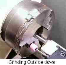 Truing
the outside facets of these same jaws is quite easy. Tighten a band
clamp around the chuck's body as seen in the photo at the left. Open the jaws so
inward pressure is applied to each jaw by the clamp. Then, grind the
outer jaw facets till all three spark out. Since each jaw comes into contact
with the grind stone just briefly during a revolution, I disengage the
spindle drive and rock the chuck back and forth by hand and about each jaw in
turn. Since you can't pass the stone beyond the inside edge of the jaw facet,
the taper in the stone could taper the outer jaw face. Here, I offset the angle
of the grinder's axis a few degrees to ensure that only the leading edge of the stone wheel
does the grinding. Finally, place several layers of masking tape on the jaw's backstop
face. If the wheel moves too far inward it will
shred the paper tape rather than accidentally grind the jaw's backstop.
Truing
the outside facets of these same jaws is quite easy. Tighten a band
clamp around the chuck's body as seen in the photo at the left. Open the jaws so
inward pressure is applied to each jaw by the clamp. Then, grind the
outer jaw facets till all three spark out. Since each jaw comes into contact
with the grind stone just briefly during a revolution, I disengage the
spindle drive and rock the chuck back and forth by hand and about each jaw in
turn. Since you can't pass the stone beyond the inside edge of the jaw facet,
the taper in the stone could taper the outer jaw face. Here, I offset the angle
of the grinder's axis a few degrees to ensure that only the leading edge of the stone wheel
does the grinding. Finally, place several layers of masking tape on the jaw's backstop
face. If the wheel moves too far inward it will
shred the paper tape rather than accidentally grind the jaw's backstop.
Shop Air
Shut Off
by
Dick Kostelnicek - HMSC Member
 The
compressed air supply lines are buried deep behind sheet rock and insulation
throughout the walls in my shop,
and there is a leak. Every 45 minutes my compressor cycles, day and night. I
put a 1/4 turn ball valve on the compressor outlet, and when I remember
to close it, the cycling ceases and doesn't wake me at night. The compressor's check valve and tank
are air tight.
The
compressed air supply lines are buried deep behind sheet rock and insulation
throughout the walls in my shop,
and there is a leak. Every 45 minutes my compressor cycles, day and night. I
put a 1/4 turn ball valve on the compressor outlet, and when I remember
to close it, the cycling ceases and doesn't wake me at night. The compressor's check valve and tank
are air tight.
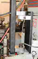
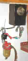
Recently I replaced the 1/4 turn ball valve with a 24 volt electrically operated valve. I found it in the lawn, watering, and sprinkler department of my home improvement store. It is rated at 150 psi, all plastic construction, and has 3/4 male NPT threads. To actuate the valve, I used a photo cell like the ones seen atop mercury vapor street lamps, also obtained at the home improvement store. Now, this photo cell has a 30 second delay feature, both on and off, built in to it. As long as the lights are on in my shop, I have compressed air available through the in-wall piping. If I just pass through the shop to the garage and use the lights for less than 30 seconds the air lines are not recharged.
Well, there are some additional components connected to the valve that you should know about. First, the photo cell itself is visible at the top of the plastic box in the photo. The cell would normally turn ON the electrically operated valve when the lights went OFF, just as it normally would turn on an outside lamp in the dark. So, I used a 110 volt relay (Radio Shack) to reverse the on-off sense of the photocell. Also, the box contains a 110-to-24 volt transformer to power the valve.
If you have no need for the time delay feature afforded by the photo cell, then connect the 110 volt side of the 24 volt transformer directly to the shop lighting circuit. Then the valve will connect the compressor to the supply lines whenever the shop lights are on.
This auto air line charge feature has worked out nicely. I get a lot more sleep from
the peace
and quiet when away from my shop.
|
Visit Our Home Page at |
 |
Right click below then select [Save
Target As...]
From Netscape select [Save Link As..]
Microsoft
Word version of this newsletter 220 KB