Volume 4, Number 8 - August
1999
Journal of the Home Metal Shop Club of Houston,
President - Keith Mitchell, V. Pres.- John Lilly, Treasurer - Gordon
Lawson, Secretary - Dean Eicher
Editor - Keith Mitchell Hm (281) 391-2406 Wk (713) 215-8123 Email kmitchl@wt.net
Membership Information Membership is open to all those interested in
machining metal and tinkering with machines. The purpose of the club is
to provide a forum for the exchanging of ideas and information. This includes,
to a large degree, education in the art of machine tools and practices.
There is a severe shortage of written information that a beginning hobbyist
can use. This makes an organization such as this even more important. For
membership information and forms, call Keith Mitchell at the phone numbers
shown above.
Notes from the President
By: Keith Mitchell
This will be short since I'm sure you would rather hear about making
chips than what I've got to say. I though the last meeting was excellent.
Tom did an excellent job of demonstrating the flexibility of his quill
tool. The presentation at the August meeting will be by John Hoff on machinery
reconditioning. John is an excellent machinist and has reconditioned several
of the machines he uses in his shop. This topic has been often requested
so this is your opportunity to get the straight info from someone who has
been there; done that.
Coming up in October we have the Third Annual Swap Meet. George Edwards
has agreed to coordinate this event. In the past Rutland has provided the
lunch. I would like to reciprocate this year and perhaps furnish Bar-B-Que
for them. Get all of that stuff you bought at last year's swap meet with
great intentions but have yet to do anything with together and do the environmentally
correct thing. Recycle!
This month's newsletter contains two excellent articles. Bill Swan produced
the CNC article and from J.D. Wise we have the first installment of a two
part article on lapping. We are getting in pretty good shape for newsletter
articles. I would like for everyone to think about a presentation they
might give. We need some help there. See you the 21st.
August Business Meeting Agenda
1. Treasury Balance
2. Swap Meet Planning
3. Recommendation on loan of Machinery Reconditioning book
4. Recommendation on purchase of digital camera for club
5. Any other business
Meeting Minutes
By Dean Eicher
Chips Meeting - 1:00 P.M. July 17, 1999, Oak Forrest Library
Attendance - 31, Two first time attendees
In the Chips Meeting the following activities took place.
1. Newsletter article author schedule - The following people have volunteered
to write newsletter feature articles: August, J. D. Wise; September, John
Lilly; October, George Carlson; November, Jan Rowland; December, Joe Williams;
and for January, George Edwards
2. Club meeting presentation schedule - The following people volunteered
to present topics of interest at club meetings: August, John Hoff, and
for September, George Carlson.
3. Feature presentation - Tom Moore presented his Universal Pillar
Tool, which was made from a casting set designed by George Thomas. Two
accessory racks were filled with tap holders, a centering tool, staking
tool, punches, rivet sets, closing punch, number and letter punch guides,
hole punches, and 1/4" socket and bit driver with T handle. Tom had also
fitted a Unimat motorized head and two drill chucks to the pillar tool.
During the ensuing questions and answers, Tom described his method of making
rivets from soft wire.
4. NC PC Board Drilling Machine - Jan Rowland demonstrated his Commodore
PET Computer controlled PC Board Drilling machine. His machine had an 11"
by 17" work surface and a resolution of 0.0025"
5. Keith Mitchell - distributed copies of his list of favorite web
pages.
6. Gordon Lawson - brought copies of Woodshop News (useful for making
patterns) and Farm Show.
7. Bill Swann - brought his copy of the book "Robotics Age" published
by Hayden Book Company. Jan Rowland's home shop built computer controlled
lathe article was published in the book.
8. Hand tapping machine - Joe Williams brought his shop made hand tapping
machine which featured a center push knob, lock ring to hold the tap up
while the workpiece is being moved into position, and a massive iron handwheel
to spin the tap out of the work when finished.
9. Linear actuator - Joe Williams showed a linear actuator he had made
from a gear motor.
10. George Carlson - brought a 12" pneumatic double acting air cylinder
he got from an EBAY auction. George also brought pictures of his shop crane,
which was made from a section of barn door track and a truck, and a curved
section of angle iron.
11. Jewelers lathe tailstock - J. D. Wise brought his universal drop-down
pivoting tailstock for a jewelers lathe, complete with centers, turret,
tools for the turret, milling attachment, slide rest tool, and cylindrical
grinder, and even other accessories (!), all nicely fitted into a wood
case. J. D. suggested "The Watchmakers Lathe" by Wade Goodrich for general
information on jewelers lathes.
HOW MUCH DOES IT COST TO CONVERT
TO CNC ?
By Bill Swann
I would like to describe my experiences and pitfalls in converting a
Bridgeport type mill to cnc operation.
Background: My approach to converting was "How do I get the job done
inexpensively and in a time effective manner." There are two broad approaches-
the servo motor route and the stepper motor route. Servos are more powerful
than steppers, and more expensive.
Servos: I know of no (PCI based) motion control card for under 1500$.
Servo motors and amplifiers are generally more expensive than step motor
drivers and steppers. Web sites featuring controller cards for servos are
the following http://www.galilmc.com OR http://www.pmdcorp.com/. I like
Galil because the card programs in plain English.
Another company which has a group dedicated to machine refits is Delta
Tau.
http://www.deltatau.com/. One source of servo drives is http://www.Yaskawa.com.
A local source for CNC software is CNC Solutions at http://www.shop-talk.com/.
I choose the stepper route.
The components in a computer controlled milling machine are as follows:
1. Computer controlling an indexer.
2. An indexer is software or hardware which coordinates motion on 2
or more axis - It provides step and direction signals to a driver.
3. Driver provides power to a stepmotor.
4. Stepmotor turns a belt, gear or leadscrew.
5. Leadscrew or belt moves the table or cutter or waterjet or EDM machine.
A word about leadscrews: Some of the factors in choosing a lead screw:
1. Accuracy over a 1 foot length.
2. Backlash.
3. Diameter and pitch.
4. Cost.
There are low backlash leadscrews (.003-.005") with selective ball
fit at an extra cost. Nook Industries (http://nookind.com/) makes a .2"
pitch x 6' long for 50$ and a ball nut for 18$ with .005- .010 " backlash.
Kerk motion products (http://www.kerkmotion.com/) makes cost effective
Teflon coated non-ball leadscrews with low backlash.
For a metal machining applications, accuracy and backlash are important
factors. Accuracy is inherent in the leadscrew. Nook lists the accuracy
as +/- 0.004" per ft on rolled ballscrews or +/- 0.001"/ft on precision
ground ballscrews. The backlash is driven to zero by having the equivalent
of 2 ball nuts back to back. The two sets of ball bearings are in compression.
This has the effect of making the screw less efficient (in terms of converting
torque to force). I use size 34 (3.4" square) stepmotors on my milling
machine with ball leadscrews (0.2 pitch) and get adequate cutting force.
The drawback is that the fast traverse speed in not as fast as I would
like.
A word about stepmotors. They are motors, which coupled with a stepmotor
driver cause rotation in discrete increments. 200 step per revolution is
standard. Most drivers can drive at 200 or 400 step per rev. More expensive
drivers divide the steps into microsteps.
(1/2, 1/4,1/8.... Microsteps per step.) Step motors have a tendency
to stall/resonate at the 200 step per rev mode at low speeds. This tendency
is lessened by running them at half step (400 steps per rev), and putting
a visco-elastic damper on the extended shaft on the rear of the motor.
The reason the choice of the number of steps per rev and the pitch of the
leadscrew is important is that the combination determines the steps per
inch. I chose 400 step/rev and .2" pitch leadscrew, giving 2000 steps per
inch linear travel. When programming a move it is nice if one could say
move 1 inch instead of 2000 steps. More about this in future articles on
programming. Step motor drivers take the step and direction signal and
convert it to proper sequencing to the 4 or 6 leads of the stepmotor. For
the electrically inclined, plans are available to build drivers. I choose
to purchase drivers. I use a 2.5 amp bi-polar driver on the milling machine
that costs 180$ from American Scientific Specialty Company. I like this
driver because it is repairable if you let the smoke out. Some drivers
are throwaway if they are burned up. Another feature that I like is that
the drive signals are opto-isolated.
Assume we have a stepmotor coupled to a leadscrew driving a milling
table. To make a move the step motor driver has to receive a step and direction
signal from the computer. Each signal is 5 vdc. The direction signal is
0 or 5vdc, corresponding to the rotation direction. The step signal is
a square wave pulse train, the frequency of which determines the speed
of the stepmotor. Some drivers take a pulse train on one pin for rotation
one direction and a signal on another pin for rotation in the other direction.
The magic between the computer and the driver is the indexer.
I use a software indexer available from Ability Systems Corp. It is
DOS based. (http://www.abilitysystems.com/). It is called Indexer LPT.
It is the least inexpensive indexer of which I am aware. Computers can
have up to 3 parallel ports. Each port drives 2 stepmotors. Of the 25 conductors
in a DB-25, the signals are step, direction, ground, forward limit, reverse
limit and auxiliary output...times 2. I use one of the available 6 axes
for a joystick/ panic stop switch. The software has a command set (different
from G Code) in English. For instance, the command for moving 2 axis is
: move: "a, 2000, b, 2000", where 2000 stands for the number of steps.
The command for traversing a circle is "circle:cw(or ccw), a ,2000,b,2000".
The cutter would move along a circular path where the center of the circle
is 2000 steps in the x direction and 2000 steps in the y direction. The
software also controls speeds.
A word on programming: The move sequence can me manually typed, one
line at a time, into an ASCII file. Then all the move and speed control
or dwell commands are executed sequentially. A profile can be created on
ACAD or other drafting packages.
So what is the cost?
1. computer- 286 or better is OK- faster computers can make faster
motion
2. Indexer LPT costs 250$.
3. Drivers- 180$ per axis.
4. Stepmotors- 180$- available at scrap yards or surplus.
5. Leadscrews- $$
Questions: Bill Swann
Photos and Commentary by Keith Mitchell
As a followup on this article I went to Bill's shop to get some pictures
of his mill conversion. In the process I saw many other things which I
felt would be of interest.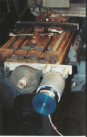
Photos 1 & 2 show how the stepper motors were mounted to the mill.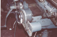 Note the cog belt and sprocket drive to increase the torque of the stepper
motors. Much of Bills work is in items produced by CNC in wood. Photo 3
shows a CNC router. This machine has a router mounted on the cross slide
which does the cutting. There are three stepper motors mounted; one on
the drive spindle, one on the cross slide, and one to traverse the cross
slide. Some unusual shapes can be produced which probably could not otherwise
be produced. Bill uses a single computer
Note the cog belt and sprocket drive to increase the torque of the stepper
motors. Much of Bills work is in items produced by CNC in wood. Photo 3
shows a CNC router. This machine has a router mounted on the cross slide
which does the cutting. There are three stepper motors mounted; one on
the drive spindle, one on the cross slide, and one to traverse the cross
slide. Some unusual shapes can be produced which probably could not otherwise
be produced. Bill uses a single computer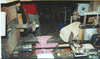 and stepper motor drivers to operate this machine and his mill. The stepper
motors are connected with plug-in connectors allowing him to quickly change
from one machine to the other. This reduces the cost since only one set
of stepper motor drivers are required to operate both machines.
and stepper motor drivers to operate this machine and his mill. The stepper
motors are connected with plug-in connectors allowing him to quickly change
from one machine to the other. This reduces the cost since only one set
of stepper motor drivers are required to operate both machines.
Flat Lapping
Part I of a Two Part Article
By: J. D. Wise
A while back I had a small part made from tool steel which needed to
be flatter and smoother than I could machine it. Lapping seemed to be the
answer, but although I knew that lapping could achieve very high levels
of accuracy, I had never actually lapped anything. Over the years I had
heard and read a number of descriptions of lapping, but many of them seemed
to contradict what the others said. So, as befits an academic, I embarked
on a program of research to discover the truth about lapping.
This article summarizes what I found.
First a disclaimer: most of this article is based on book learning rather
than practical experience. My "formal" training in metalworking did not
treat abrasive methods as precision techniques: precision work was done
in the lathe and the mill, the grinder was used for rough shaping tool
bits by hand, and lapping was something we did to the valves in the car's
engine to make it run better.
Part I. Background
1. Precision Machining
The lathe and mill are the traditional precision machine tools,
but at some point they run out of steam. Taking a cut of 1/10,000 inch
with a good surface finish requires a tool which is carefully
shaped, carefully aligned, and very sharp. And of course a workpiece
that's soft enough to be cut by the tool in the first place,
and a tool which is hard and tough enough to stay sharp for the duration
of the cut.
The next level of precision is typically achieved by abrasive techniques,
specifically grinding, honing, and lapping.
Precision grinding is basically an extension of milling and turning
where the tool bit or cutter is replaced by a grinding wheel. This
affords several improvements: harder material may be worked, smaller cuts
taken, and a smoother finish produced. But as in the lathe and mill, the
resulting accuracy still depends on the precision of the machine.
So, for example, cylindrical grinding can be done in the lathe with
a toolpost grinder. Although finer cuts can be taken, the work will be
no rounder or straighter than turned work. Also, because normal forces
are higher in grinding than in turning, accuracy and surface finish can
deteriorate due to deflection or chatter.
The precision produced in grinding depends on both the machine and on
the wheel. However, there is another class of abrasive operations,
typified by honing and lapping, where the precision of the machine
contributes little or nothing to the quality of the final result.
Lapping in particular seems like a miraculous process: using only simple
hand tools, it can produce surfaces which are perfectly flat, perfectly
round, perfectly smooth, perfectly sharp, or perfectly accurate.
Although not actually miraculous, nor capable of absolute perfection,
lapping can accomplish some fairly impressive feats. Under the right circumstances
it can:
1. Impart or improve precise geometry (flatness, roundness, etc.).
2. Improve surface finish.
2a.Improve surface quality.
3. Achieve high dimensional accuracy (length, diameter, etc.).
4. Improve angular accuracy (worm gears, curvic couplings, etc.).
5. Improve fit.
6. Make tools sharper.
The technique that machinists call lapping appears, with occasional
variations, in a variety of other fields. The dictionary definition of
lap is "a rotating wheel or disk holding an abrasive or polishing powder
on its surface, used for gems, cutlery, etc." In fact the origin of the
word comes from "lapidary" (from the Latin lapidarius meaning "of stone")
where such a wheel is used to cut, shape, and polish gemstones. Other examples
of related techniques include the watchmaker's polishing operations, the
woodworker's shaping of plane soles and irons, and the grinding and polishing
of mirrors and lenses in optical work.
2. Abrasive Basics
Let's start by looking at how an abrasive works. Figure 1a shows an
abrasive grain lying on the surface of a workpiece. If we apply a force,
a high level of stress will be produced at the point of contact. Since
the grain is harder than the work, it will penetrate into the surface of
the work, as shown in Figure 1b. If the pressure is small (within the elastic
limit of the material) the deformation will not be permanent.
As we increase the pressure and the grain is forced further into the
surface, what happens depends on the nature of the material. For a
ductile material, when the elastic limit is exceeded, the material will
be displaced by plastic flow (Figure 1c). For a brittle material, when
the elastic limit is exceeded, a chip will be dislodged by brittle fracture
(Figure 2).
Material Removal
Now, suppose that after pressing the grain into the surface of the work,
we move it laterally. If the pressure is light and we haven't exceed the
material's elastic limit, the material will move out of the way ahead of
the grain and return to its original place behind, like a boat moving slowly
through water. At this level of pressure, the grain is simply rubbing along
the surface of the work. Because of the friction between the grain and
the work, force is required to move it and heat will be produced.
If we increase the force past the yield point, the workpiece material
will be permanently displaced into a raised region on either side of the
groove formed by the grain, as in a plowed furrow. This is called, appropriately
enough, plowing, and is accompanied by the production of heat, both from
the sliding friction between the grain and the work, and from the internal
friction of the material as it is deformed.
As the pressure and resultant depth of penetration continue to increase,
the amount of material built up in front is more easily displaced ahead
of, rather than to the side of the grain, and a chip is formed (Figure
3). We have finally reached the regime of cutting.
Figure 3.
This is similar to the way in which a chip is produced by a cutting
tool, but because of the highly negative effective rake angle it is
formed by extrusion rather than by shear. Note that in the cutting
regime, both plowing and rubbing are also taking place. In a brittle material,
there will be a succession of fractured chips, rather than a continuous
extruded chip.
The effort required to remove a given amount of material (called the
"specific energy") depends on the size of the chip. Regardless of the chip
size, a certain amount of the applied lateral force goes into rubbing and
plowing, which removes no material. At the onset of cutting, these forces
predominate, and a large force is required to produce a small chip. As
the normal force increases, the depth of penetration and hence the thickness
of chip increase and a greater proportion of the applied force goes into
producing the chip. Hence as the size of the chip increases, the work required
to remove a given volume of material decreases.
This is why a coarse grit removes material faster than a fine grit:
With coarse grit, a small number of large grains penetrate deeply into
the work, producing a small number of large chips with high efficiency.
With a finer grit, the applied normal force is spread over a larger
number of smaller grains so the depth of penetration of each will be less.
More of the lateral force goes to rubbing and plowing and less to removing
material.
Abrasive Wear and Breakdown
So much for the workpiece, what happens to the abrasive grain itself?
Although very hard, it's not infinitely strong and is subject to failure
or breakdown via several mechanisms.
Because it is typically quite brittle, it will fracture when local stresses
exceed its elastic limit. Since stresses are highest at the sharpest points,
these tend to be the first to break. Depending on its friability, the grain
may either fracture in such a way as to leave another sharp point or edge
behind, or the sharp corners may be broken off, leaving behind a smoother,
less sharp surface.
If the grain is held in a fixed orientation, this will take the form
of a "wear flat." If free to rotate, it will eventually assume a "round"
shape.
This wear can be accelerated chemically. For example, the mutual affinity
of iron and carbon means that a diamond will wear rapidly when used to
grind steel, in spite of its much higher hardness.
