Volume 6, No. 12 - December, 2001
|
|
Volume 6, No. 12 - December, 2001 |
|
|
|
|
|
|
President - |
Vice President - |
||
|
Treasurer - |
Secretary - |
Ed Gladkowski |
|
|
Web Master - |
Editors - |
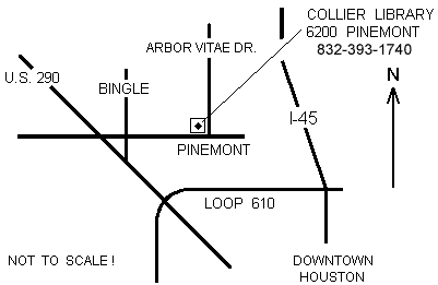
1:00 p.m., Collier Library, 6200 Pinemont, Houston, Texas; 30 members attended.
President Dennis Cranston asked for suggestions concerning possible uses of surplus funds. He also announced a casting workshop scheduled for 1:00 p.m. Saturday, December 1, at the Houston Area Live Steamers site in Zube Park.
Dick Kostelnicek reported The club's website has a new domain name, www.HomeMetalShopClub.org. The cost of hosting the website is $120.00 per year.
A suggestion was made to update Modeltec and Village Press Publications with current club information. Secretary Ed Gladkowski has notified Modeltec and will follow up with Village Press.
|
|
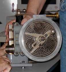
Tom Moore demonstrated and explained equipment and methods for dividing in the Myford lathe. He also, spoke about ceiling fans. |
|
|
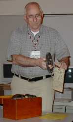
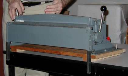
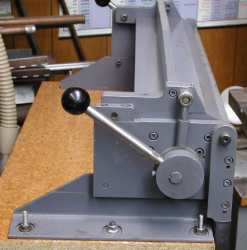
Joe Williams showed his home shop built sheet metal brake (see article below), and a set of gears for a Brown & Sharpe universal dividing head. |
|
|
|
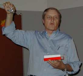
Dennis Cranston showed some model wheel castings made using Za12 alloy in a metal mold. |
|
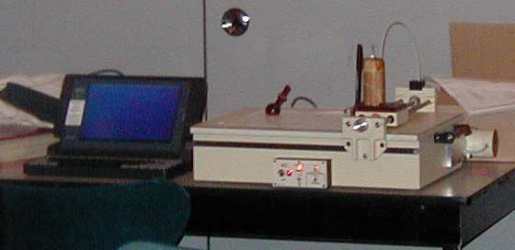
Jan Rowland demonstrated his homemade plotter used to prove out programs for his homemade cnc lathe!
|
|
|
|
Joe Scott told of some recent experiences on a visit to England. |
|
A Sheet Metal Brake |
|
The æhome madeÆ Sheet Metal Brake was presented at the November HMSC meeting. It is fabricated from hot rolled steel plate and angle that was picked up from a scrap bin at my friendly fabrication shop. The only purchased items were the ball knobs and the socket head cap screws. The unit is a good project for the milling machine, band saw (or torch and grinding) and drill press with the only welding being done at the crank assembly.
 The
unit has capacity to handle stock that is 24 inches wide. The operating handle
is a ¢ inch diameter, 5 inch long, section of stainless steel bar with a 1-3/8
inch plastic ball and wrench flats. The rod is screwed into the eccentric unit,
one on each side, that is 2-3/8 inch in diameter and has a reduced section for
the crank shaft. The crank section has an extension welded on and threaded for
the revised ball connection. The self aligning ball was removed to provide a
larger diameter shaft. The eccentrics, on each side of the unit, are connected
by a 5/8 inch diameter shaft keyed to each end with the shaft running in a bronze
bushing at each end. This keeps both sides in synch. They are adjusted to provide
over center locking with the material being bent. The base is mounted
on a pair of steel angle sections, 1/4 x 2 x 3 inch, that have the anchor bolt
holes and a milled section to provide a stop and a parallel mounting surface.
The upper blade is made from a ¢ x 4¢ x 24 inch section with a nominal 30 degree
face end with a 1/16 inch flat on the end.
The
unit has capacity to handle stock that is 24 inches wide. The operating handle
is a ¢ inch diameter, 5 inch long, section of stainless steel bar with a 1-3/8
inch plastic ball and wrench flats. The rod is screwed into the eccentric unit,
one on each side, that is 2-3/8 inch in diameter and has a reduced section for
the crank shaft. The crank section has an extension welded on and threaded for
the revised ball connection. The self aligning ball was removed to provide a
larger diameter shaft. The eccentrics, on each side of the unit, are connected
by a 5/8 inch diameter shaft keyed to each end with the shaft running in a bronze
bushing at each end. This keeps both sides in synch. They are adjusted to provide
over center locking with the material being bent. The base is mounted
on a pair of steel angle sections, 1/4 x 2 x 3 inch, that have the anchor bolt
holes and a milled section to provide a stop and a parallel mounting surface.
The upper blade is made from a ¢ x 4¢ x 24 inch section with a nominal 30 degree
face end with a 1/16 inch flat on the end.  A
reinforcing section of bar stock , ¢ x 2¢ x 22-11/16 inch, is bolted to the
upper blade with counter sunk socket head cap screws. The pivot end sections
are made from 3/4 x 1¢ x 5¢ inch stock. The mounting bolts holes, for the fixed
side of the pivot are slotted to provide adjustment of the upper blade for different
thicknesses of material. The side sections are 3/4 x 1¢ x 5¢ inch long. The
pivots are ¢ inch socket head shoulder bolts. The main frame end sections are
¢ x 4¢ x 7 inch and are contoured on the pivot end to provide clearance for
the operating handle. The folding blade is a section of ¢ x 4¢ x 25-5/16 inch
with the handles bolted to the blade. The handles have a section of heat
shrink material. The pivots on each end are set to have the center line
parallel to the edge of the folding blade. The pivots are socket head shoulder
bolts running in a needle bearing at each end. The bearings were salvaged from
a scrapped airplane. I have thought about cutting some slots in the upper blade
to allow the folding of pans, but the unit has served well with out that feature.
If I was to rebuild the unit, I would make it with adjustable fingers, but that
gets complicated for a casual use brake.
A
reinforcing section of bar stock , ¢ x 2¢ x 22-11/16 inch, is bolted to the
upper blade with counter sunk socket head cap screws. The pivot end sections
are made from 3/4 x 1¢ x 5¢ inch stock. The mounting bolts holes, for the fixed
side of the pivot are slotted to provide adjustment of the upper blade for different
thicknesses of material. The side sections are 3/4 x 1¢ x 5¢ inch long. The
pivots are ¢ inch socket head shoulder bolts. The main frame end sections are
¢ x 4¢ x 7 inch and are contoured on the pivot end to provide clearance for
the operating handle. The folding blade is a section of ¢ x 4¢ x 25-5/16 inch
with the handles bolted to the blade. The handles have a section of heat
shrink material. The pivots on each end are set to have the center line
parallel to the edge of the folding blade. The pivots are socket head shoulder
bolts running in a needle bearing at each end. The bearings were salvaged from
a scrapped airplane. I have thought about cutting some slots in the upper blade
to allow the folding of pans, but the unit has served well with out that feature.
If I was to rebuild the unit, I would make it with adjustable fingers, but that
gets complicated for a casual use brake.
This unit has served me well for many years. I welcome any one wanting to build a similar unit come to my shop and give the unit a trial run and check dimensions or fabrication features.
|
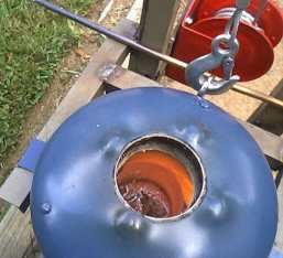
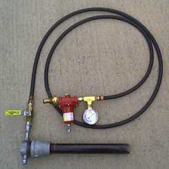
Freon Bottle Foundry Building the Burner by Larry Hill - HMSC member In last month's newsletter I described the furnace. Here I explain construction of the propane burner. |
Introduction: The design process for the burner was not very scientific and relied on work previously done by others. The burner that I build is a venturi style, or naturally aspirated, burner. Ed Gladkowski, HMSC member, uses a similar one in his foundry. My furnace is relatively small and does not require a lot of heat to bring the aluminum charge to melting temperature. As it turns out, the burner that I built, is more that adequate for the freon bottle foundry.
Construction Notes: The burner uses off-the-shelf parts that can be
found at most local hardware stores.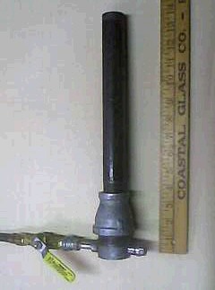
Furnace Performance: The burner has proved to be an excellent fit for the furnace. The burner will light without a problem inside the furnace. When withdrawn from the tuyere, a barrel flare extension is required to reduce the velocity of the gas in order for the burner to stay lit. With the regulator set at 2.5 psi, a full crucible of aluminum will melt in less than 15 minutes. I should be able to use this burner in a larger furnace or generate more heat to melt bronze or brass by increasing the gas pressure.
In retrospect, I wouldnÆt do anything different, except buy a cheaper regulator (I paid $40 for the Fisher Controls regulator), and add quick connect fittings on each end of the hose assembly.
|
Patrs List: |
|
Freon Bottle Foundry
-
Part 1
Freon Bottle Foundry
-
Part 3
|
by Rod Shampine - HMSC member |
|
|
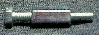
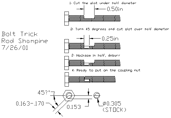
This is a sneaky puzzle for a machinist. The original that I measured was Aluminum, but I think it works better in standard galvanized parts. It's more innocent looking. This toy can easily be scaled to whatever size you want. For the one that I made, I used a 5/16-18 coupling nut and a 2-1/2 inch long 5/16-18 full thread bolt from the hardware store. Cut a slot in the bolt to just under half diameter (a couple of thousandths under), rotate it 45 degrees and cut a shorter slot at 7 to 12% over half diameter and then cut it in half at the middle of the long slot. Deburr the heck out of it and then put them together. The coupling nut will go onto the whole assembly and cover the junction. If it is made right, and you hold the hex head, the nut will only screw on! If you hold the thread end it, will only unscrew! The only way to find the joint is to take the nut off completely; it will be hidden if the nut is run all the way onto the bolt. Basically, the 45 degree cut acts as a cam to force the two bolt halves out radially to grip the inside of the nut. Great fun to watch people try and turn it! |
|
|
|
The next meeting will be held on Saturday December, 8 2001 at the Collier Library 6200 Pinemont, Houston, TX at 1:00 pm. Bring along a work in progress. Visit Our Web Site |
 |