Volume 7, No 12 - December, 2002
|
|
Volume 7, No 12 - December, 2002 |
|
|
|
|
|
| President - |
Vice President - |
||
| Treasurer - |
Secretary - |
||
| Webmaster - |
Editors - |
||
|
|
|
SIG Coordinator - |
Statement of Purpose
Membership is open to all those interested in machining metal and tinkering with machines. The club provides a forum for the exchanging of ideas and information. This includes, to a large degree, education in the art of machine tools and practices. Our web site endeavors to bring into the public domain written information that the hobbyist can understand and use. This makes an organization such as this even more important.Business Meeting
Minutes are sent via email or regular mail to club members.
Regular Meeting
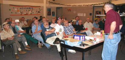 Collier Library. 6200 Pinemont, Houston, Texas. November 9, 2002. 2:00 pm. Attendees: 40 including 3 visitors: Mr. Fuselier, Mr. Stimac, and Mr. Uberohl.
The meeting was delayed 1 hour while another group used the facilities. Next meeting commences at 2:00 p.m. December 14, 2002 at the Collier Library. Subsequent meetings will revert to the normal 1:00 p.m. time.
2003 club dues must be paid by the next meeting. Delinquents will be dropped from club membership.
Dennis Cranston will bring selected library materials to the meeting for check
out: books one month, videos the next.
Presentation
|
|
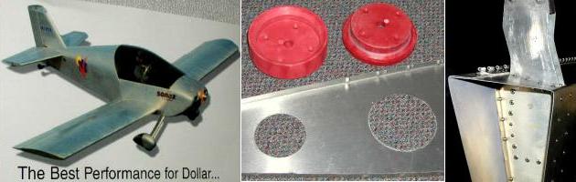
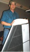
Barry Leinhart and Val Vaugn gave an interesting talk, demonstration and video about the all-aluminum “SONEX” home-built airplane they are building. |
|
Show and Tell
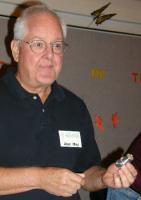
Alan May showed a ball joint tripod adaptor. |
Bill Swan showed a 5-lead, Teflon-coated leadscrew and a CNC-produced mahogany lamp base. |
|
|
|
Ed Gladkowski brought one of his casting flasks |
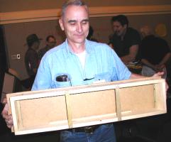
Joe Williams showed some shaper replacement parts, tooling, and a shaper drive door ( by Art Volz) . |
Visitor Maury Uberohl displayed a partially complete, beautiful model of a Corliss steam engine he is building from his own lost wax castings scaled from an actual engine still in existence. |
No activity this Month.
Computer Numerical Control SIG
No activity this Month.
Featured Articles
Variable Frequency Drive and Motor Installation
by J. R. (Joe) Williams - HMSC Member
 The
time had finally come to replace the drive motor for my lathe, a 13 in.Clausing-Cholchester. The
old one was 20 years old and had always had a slight vibration that could
be felt with the lathe running. Several years ago, I considered installing
a PM - DC, permanent magnet - direct current, motor but found I could
not physically install a large horsepower DC motor in the space available
due to its extroardary length. Some years ago a HMSC member,
Ron Blair, installed a VFD drive on his lathe and made a formal presentation
at a meeting. This helped me make up my mind to go the VFD route. After reviewing
many different drives and motors, I choose a Yaskawa drive and Marathon
motor. Older motors may not be inverter rated, since the winding insulation
may not be capable of withstanding the voltage spikes generated by the
VFD drive. The VFD drive is rated for 5 hp when supplied
with 3-phase power. However, when single phase is used, it will handle only
a 3 HP motor. My lathe originally had a 5 HP motor but when I purchased it, I
had the dealer change the motor to single phase, 230 volt, 3 HP. It
has worked well for me for around 2500 hours. The 3 HP can make more chips than
I can handle and I would not even consider using the full 5 HP of the original
motor in a small shop.
The
time had finally come to replace the drive motor for my lathe, a 13 in.Clausing-Cholchester. The
old one was 20 years old and had always had a slight vibration that could
be felt with the lathe running. Several years ago, I considered installing
a PM - DC, permanent magnet - direct current, motor but found I could
not physically install a large horsepower DC motor in the space available
due to its extroardary length. Some years ago a HMSC member,
Ron Blair, installed a VFD drive on his lathe and made a formal presentation
at a meeting. This helped me make up my mind to go the VFD route. After reviewing
many different drives and motors, I choose a Yaskawa drive and Marathon
motor. Older motors may not be inverter rated, since the winding insulation
may not be capable of withstanding the voltage spikes generated by the
VFD drive. The VFD drive is rated for 5 hp when supplied
with 3-phase power. However, when single phase is used, it will handle only
a 3 HP motor. My lathe originally had a 5 HP motor but when I purchased it, I
had the dealer change the motor to single phase, 230 volt, 3 HP. It
has worked well for me for around 2500 hours. The 3 HP can make more chips than
I can handle and I would not even consider using the full 5 HP of the original
motor in a small shop.
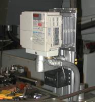
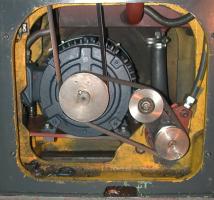
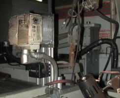
The physical installation of the new motor was the difficult part, as it fills all the space available. I ground out a section of the lathe's base inside rib structure in two places to make moving the motor into place easier. I found I could use two of the old motor mounting holes in the mounting plate and moved the motor closer to the pivot providing additional clearance. The motor plate, on the belt adjustment side, is provided with springs above and below the plate to reduce any vibrations, a remnant from the old motor days. I installed new belts as the old one was showing signs of being very tired. The belt for the lube oil pump was replaced when the oil was recently changed. The junction box on the motor was turned over to so the original wiring could be reused.
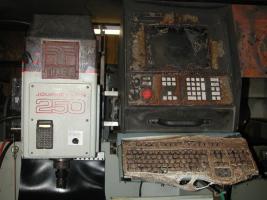
The VFD controller was mounted on a section of salvaged flat aluminum extrusion with several key way slots. It was notched, bent, and welded to the angle required to fit the backside of the lathe and bolted to a back panel. The wiring connections were made with flexible metal PVC covered conduit for shielding purposes. The original design was changed so an additional conduit was required. This is so I can utilize the lathe's existing ON-OFF push button controls. A salvaged hour meter was installed below the VFD controller. I have an existing hour meter that was retained and it is mounted in the base area of the lathe.
The set up of the VFD was without problems but it did require reading the set up instructions very closely. There are about 180 parameters that can be operator set. The printed material is in very small type and that does not help my tired old eyes. I found out later, from the distributor, a larger type manual is available. The unit worked when the power was applied. The VFD controller has a set of relay contacts that are used for the Hour Meter control.
I could have merely installed a new three-phase motor and operated it from a rotary phase converter but decided to the VFD route and have the speed control feature. The only problem with low speed operation is the lube pump turns too slow to deliver lube oil to the head. This drops off at about 30 cycles - 900 motor RPM. The unit will run well at low speeds on 15 to 20-cycle power. I am undecided about the lube system as a solution for low speed operation would be to install an additional small motor to drive the lube pump. Right now, I can easily obtain around 15 RPM on the spindle and retain lube oil supply. As a bonus, the lathe's overall noise level was reduced considerably.
Would I do it over? Yes! Cost? Plenty! It was not a low cost system but when you get to my age it becomes what I want, not what I need. Surplus, low cost, VFD systems are available and many would do a fine job, but they are a generation or more older.
 Soon
after the VFD installation, I had a disastrous fire in my shop. I'll soon
be rebuilding my mill and lathe. I had a total of 15 hours on the
drive when the fire occurred. A new drive unit is on order and it will be put in
the same location. Hopefully, none of the wiring will need replacing.
Soon
after the VFD installation, I had a disastrous fire in my shop. I'll soon
be rebuilding my mill and lathe. I had a total of 15 hours on the
drive when the fire occurred. A new drive unit is on order and it will be put in
the same location. Hopefully, none of the wiring will need replacing.
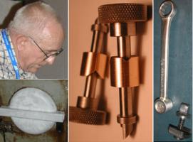
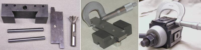
by Dick Kostelnicek - HMSC Member
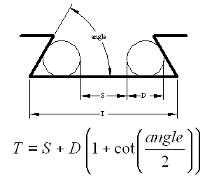
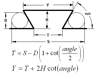 If
you want to make tooling with dovetails, such as an Aloris ®
style tool holder, you'll need to be able to accurately measure a dovetail's
T-width. This is the point where the edge of the dovetail cutter's
face contacts the work. The two sketches show the two-cylinder method
for determining the width for both internal and external dovetails. The formulas
involve (1 + cot (angle / 2)) which can be replaced by 2.732 if you use a 60
degree cutter. By cutting and then measuring an internal test dovetail,
you can determine the face diameter of your cutter.
If
you want to make tooling with dovetails, such as an Aloris ®
style tool holder, you'll need to be able to accurately measure a dovetail's
T-width. This is the point where the edge of the dovetail cutter's
face contacts the work. The two sketches show the two-cylinder method
for determining the width for both internal and external dovetails. The formulas
involve (1 + cot (angle / 2)) which can be replaced by 2.732 if you use a 60
degree cutter. By cutting and then measuring an internal test dovetail,
you can determine the face diameter of your cutter.
In order to perform the measurements, you'll need two rods of accurate diameter. I use 1/4 in. dowel pins. For the internal dovetail, an adjustable parallel is a must. Making the measurements is demonstrated in the accompanying photos.
|
The next meeting will be held on Saturday December 14, 2002 at the Collier Library 6200 Pinemont, Houston, TX at 2:00 p.m. Bring along a work in progress to show. Visit Our Web Site |
 |
Right click below then select [Save
Target As...]
From Netscape select [Save Link As..]
Microsoft
Word version of this newsletter 263 KB


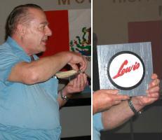 Art
Volz brought another of his bag of tricks, containing, among
other things, homemade shaper toolholders, a Logan shaper cover
casting and another one made from an old skillet that is indistinguishable
from an original cover. Also, a wooden pattern for an Art
Deco style cover for a Lewis shaver and a wood mock-up for a vise
for a Lewis mill.
Art
Volz brought another of his bag of tricks, containing, among
other things, homemade shaper toolholders, a Logan shaper cover
casting and another one made from an old skillet that is indistinguishable
from an original cover. Also, a wooden pattern for an Art
Deco style cover for a Lewis shaver and a wood mock-up for a vise
for a Lewis mill.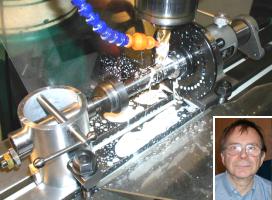 Dick Kostelnicek showed further progress on his car battery
powered bandsaw blade welder, and a homemade tailstock for a budget
brand spin-indexer. He also showed the T-slot locating lugs
he added to the spin-indexer.
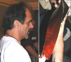
Dick Kostelnicek showed further progress on his car battery
powered bandsaw blade welder, and a homemade tailstock for a budget
brand spin-indexer. He also showed the T-slot locating lugs
he added to the spin-indexer.