 Ron Blair discussing
Variable Speed Drive applications
Ron Blair discussing
Variable Speed Drive applications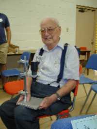 John Korman with
his Mini Drill Press
John Korman with
his Mini Drill Press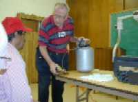 Bob Lang with his
Rudy Kouhoupt Engine
Bob Lang with his
Rudy Kouhoupt Engine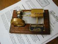 Close up of Bob
Lang's engine
Close up of Bob
Lang's engine
Membership Information Membership is open to all those interested in machining metal and tinkering with machines. The purpose of the club is to provide a forum for the exchanging of ideas and information. This includes, to a large degree, education in the art of machine tools and practices. There is a severe shortage of written information that a beginning hobbyist can use. This makes an organization such as this even more important. For membership information and forms, call Keith Mitchell at the phone numbers shown at the left.
Notes from the President
By: Keith Mitchell
The December meeting will be held at the Collier Library located at 6200 Pinemont. I think this location will better meet our growing needs. The business meeting will move also to Lyndon's Pit Bar-B-Q located at 13165 Northwest Freeway. This is in the same strip center with Woodcraft and just North of the intersection of 290 and Pinemont.
The foundry group meeting following the main meeting drew a lot of interest. >From my analysis of the comments at the meeting and subsequent e-mails it appears that the interests are in three general areas; Gas fired crucible furnaces, Electric fired crucible furnaces and Cupolas/iron melting furnaces. I've researched several of the books loaned by other club members and found some good info on gas fired furnace construction. I would like to continue our sessions following the regular meeting to continue developing the knowledge base. If you have any show and tell items for the next session please bring them.
This month's newsletter contains an excellent article by Joe Williams on the hand tapper he brought in several months ago. He has taken the time to produce dimensioned drawings for this project. The December presentation is by Keith Mitchell and J.D. Wise on work holding. I think we all recognize the benefits of being able to make quick, accurate and repeatable setups.
The Member Handbook is almost ready to issue. Vance Burns is doing some final cleanup of formatting and checking. I think this book will benefit everyone. We propose to distribute the book in one of three formats: Hardcopy, Office 97 (Word and Excel), or Adobe Acrobat. In the Office 97 and Adobe formats key words in the magazine index can be searched. I find this to be a valuable feature. We would like to distribute a copy of this to everyone but will need to know what format you prefer. Please let me know your desires by e-mail or at the meeting we will be taking a poll.
At the last meeting we passed out cards to collect the information for
the Suppliers List. Please fill these out and bring to the next meeting
starting with your most obscure supplier and working to the better known
sources. Keep in mind that we do not plan to distribute this information
outside the club so your "secret" sources are protected.
November Meeting Minutes
By: Dean Eicher
Chips Meeting - 1:00 P.M. November 20, 1999, Oak Forrest Library
Attendance - 34, No new members or visitors
In the Chips Meeting the following activities took place.
1. New Meeting Location The December 18 meeting location will be at
the Collier Library, 6200 Pinemont Dr.
2. Feature Presentation - Ron Blair talked about variable speed AC
motors and motor drives for machine tools. Commercially available speed
controllers (for example, those made by Magnetek) change the motor speed
by changing the AC frequency to the motor. The controllers also adjust
their output voltage to the motor to keep it from overheating at frequency
extremes. Ron said that adding a motor speed controller to a machine tool
is frequently complicated by the fact that many motors windings will break
down at the higher voltages from controllers, especially the ones that
use pulse width modulation techniques to simulate variable output frequencies.
Modern motors incorporating windings with insulation spike resistant (ISR)
wire are specially designed to work with controllers, and you may find
it necessary to replace your machine's motor when you add a controller.
3. Bob Lang - brought a steam engine he built from a Rudy Kouhoupt
design.
4. John Korman - talked about Bob Arnold's medical condition and mentioned
the lathe and drill press he is selling.
5. Jan Rowland - brought the headstock of a CNC lathe he is building.
6. John Korman - brought a telescoping extension for a marker and a
sensitive drill press designed around a Dremel tool.
7. Joe Williams - brought a cutting tool he made for cutting a circular
groove. Joe also had a nice chuck workpiece spacer with pads on its outer
surface to keep it centered between the chuck jaws and vibration free.
8. Keith Mitchell - brought three sizes of torch cutting tips and showed
that the preheat holes on the perimeter of the tips are the same size,
but the center hole for the oxygen varies according to the capacity of
the tip. Keith also talked about how oxygen pressure should be adjusted
for cutting different thickness materials.
November Meeting Photos
| Ron Blair discussing
Variable Speed Drive applications |
John Korman with
his Mini Drill Press |
| Bob Lang with his
Rudy Kouhoupt Engine |
Close up of Bob
Lang's engine |
Taps must be carefully aligned to the work to prevent tap breakage when
tapping holes. 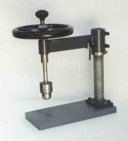 This
unit has been very useful in my shop as I make a variety of small parts
requiring threaded holes. I was given several (new) cast iron gate valve
hand wheels and while looking for a future use for them, the construction
of the tapping unit became a reality. One handwheel with five plastic file
handles attached to the outer diameter wound up as a 'ships wheel' for
my grandsons tree house, one was installed on my arbor press, and one on
the tapping unit. The 'flywheel" action of the heavy wheel makes for easy
tapping while the large plastic knob on top of the shaft is used to assist
in starting the larger taps and lifting the shaft and tap from the work.
The unit has been in use in my shop for several years and I have not broken
a tap while using the unit.
This
unit has been very useful in my shop as I make a variety of small parts
requiring threaded holes. I was given several (new) cast iron gate valve
hand wheels and while looking for a future use for them, the construction
of the tapping unit became a reality. One handwheel with five plastic file
handles attached to the outer diameter wound up as a 'ships wheel' for
my grandsons tree house, one was installed on my arbor press, and one on
the tapping unit. The 'flywheel" action of the heavy wheel makes for easy
tapping while the large plastic knob on top of the shaft is used to assist
in starting the larger taps and lifting the shaft and tap from the work.
The unit has been in use in my shop for several years and I have not broken
a tap while using the unit.
(1) Base
The base was fabricated from a steel plate "drop" 6 inches wide by
14 inches long and one inch thick. It was run thru a Blanchard surface
grinder to provide a good flat surface. Four holes were drilled and tapped
(3/8-16 NC) for the support column and one for clearance for a tap (9/16
dia) . This hole should be marked and drilled after assembly of the head
unit to place the hole directly under the center of the head.
(2) Column
The support column was made from a section of 1-1/4 inch schedule 40
steel pipe, 13 inches long, with the ends machined square. The base for
the column is made from hot rolled steel bar 1/2 inch thick, 3 inches by
4 inches, with four clearance holes for 3/8 inch SHCS. A 1/2 inch diameter
hole is drilled in the middle of the bar to permit the use of a section
of threaded rod to hold the base securely to the pipe while it is welded
to the base. After welding the bottom of the base was machined true with
the pipe section in the lathe. The column base is attached to the main
base plate with four 3/ 8-16 x 1-1/4 SHCS. The OD of the column could be
machined, but the material on hand was cadmium plated and was satisfactory
for this purpose in the 'as received' condition.
(3) Handwheel
The handwheel is a commercial item and made of cast iron. The wheel
was chucked in the lathe and indicated true with the bore and the machined
boss. It was bored to one inch in diameter for a steel adapter bushing.
A 1/4 inch wide by 1/8 inch deep key way was broached to prevent the insert
turning when in use.
(4) Handwheel Insert
A steel insert with a one inch OD and a 0.625 bore and with a flange
on the lower end was machined to go in the handwheel and has two key ways
- a 1/4 inch one on the outside and a 1/8 inch one in the bore. The insert
has a 1/8 inch thick flange on the lower end to provide a bearing surface
on the support bushing. The length of the insert was made to match the
finished length of the handwheel. The key way, in the bore, has a 1/8 inch
section milled in the faces of the insert, 1/4 inch long, for the main
drive key. The insert was installed with a key and "Loctite".
(5) Drive Key
The drive key is a captive key, with a nominal 1/8 inch square cross
section, with a 1/4 inch long section on each end. This forms a "C" section
and when installed in the insert in the hand wheel, provides the drive
member and is retained and will not fall out when the main shaft moves
vertically.
(6) Drive Shaft
The drive shaft was fabricated from a section of 5/8 inch diameter
stainless steel bar stock, 13 inches long with a 1/8 inch key way cut 6-1/4
inches long form the top end. The lower end is threaded 5/8-16 for 0.700
inches to fit a a 1/2 inch drill chuck . The threaded section is short
enough to provide a 5/8 inch diameter shaft section to pilot in the drill
chuck. The top end is drilled and tapped 5-16 -24 NF for a 2 inch plastic
knob.
(7) Safety Collar
A clamp collar was machined from a 2-5/8 inch diameter section of stainless
steel that is 1/2 inch thick. It is bored to a free fit over the pipe column
and has a cross drilled hole and milled section to provide clearance for
a 1/4-20 SHCS. After the clearance section for the head is milled and the
drilled hole is completed, the hole is tapped 1/4-20-NC and then the collar
is saw cut. This clamping action allows the head to me moved in a controlled
manner.
(8) Support Arm Assembly
The support arm assembly is a weldment with a tubular section on each
end of a rectangular bar stock center member. The drive end is a section
1-5/8 inches in diameter, 2-1/8 inches long , with a one inch hole drilled
thru the center (this will be bored out later to size after the welding
is completed). A 1/2 inch slot is milled on the OD lengthwise for alignment
of the bar section while welding. The center section is hot rolled steel
bar stock, 1/2 inch thick and 2 inches wide by 7-3/4 inches long. The column
end is a steel bar 2-3/8 inch diameter by 3-5/8 inch long with a 1-1/2
inch hole drilled thru (this will be bored out later after welding). Two
slots are milled with a ball end mill by 9/32 deep, on 2 inch centers for
clamp screw members. A 1/2 inch wide slot is milled on the opposite side
for the bar section. Two pieces of 9/16 diameter steel bar, 1-3/4 inches
long are welded in place for the clamp screws. They are drilled and tapped
before welding in place. The 1/2 inch slots provide alignment for the parts
while welding. After the assembly is welded on both ends and including
the clamping sections, the bar section is placed in the milling machine
vise and both ends are bored to size, the small end for the drive bushing
and the other end for the support column. Both holes are bores in one clamping
to provide true alignment. The next step is to saw cut the clamp end.
(9) Shaft Guide Bearing Assembly
The guide unit was made as a separate item with the thought of using
the unit for other purposes similar to the G.H. Thomas Universal Pillar
Tool. The assembly is made from a 1-1/4 inch diameter steel bar, four inches
long, with a 3/4 inch bore thru and bronze bushings inserted in each end
for the drive shaft. The bushings are 1/2 inch long and are a nominal 7/8
inch OD. The bushings were pressed in and bored to size. The guide section
is 1.125 OD diameter, 3-1/2 inches long, with the large end knurled for
easy handling.
(10) Shaft Holding Collar
To assist in changing taps, a small locking collar with a screw was
provided. The collar is 1-1/4 inch in diameter aluminum, and is 1/2 inch
thick and is knurled on the OD. The locking screw has the end turned down
to fit freely in the 1/8 inch key way in the drive shaft.
