Volume 9 , No 2- February 2004
|
|
Volume 9 , No 2- February 2004 |
|
|
|
|
|
| President - |
Vice President - |
||
| Treasurer - |
Secretary - |
||
| Webmaster - |
Editors - |
||
| Founder - |
SIG Coordinators - |
Statement of Purpose
Membership is open to all those interested in machining metal and tinkering with machines. The club provides a forum for the exchanging of ideas and information. This includes, to a large degree, education in the art of machine tools and practices. Our web site endeavors to bring into the public domain written information that the hobbyist can understand and use. This makes an organization such as this even more important.Regular Meeting
 Collier Library, Houston Texas, 1:00 p.m., January
10, 2004. 34 members were present including 4 guest, San Gurts, TimTaylor,
Marc Cohn, and Steve Hall.
Collier Library, Houston Texas, 1:00 p.m., January
10, 2004. 34 members were present including 4 guest, San Gurts, TimTaylor,
Marc Cohn, and Steve Hall.
Business Meeting
Minutes are sent via email or regular mail to club members.
Presentation
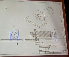

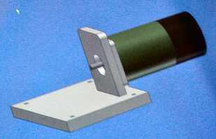
Bill Swann, HMSC Member, gave a live presentation on a notebook computer of the CAD CAM program Auto Desk Inventor. Bill designed a base and motor bracket in 3D design mode.
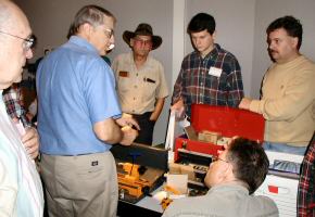
Show and Tell
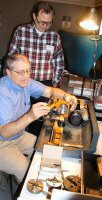
Ed Gladkowski showed a drill spindle that mounts on a lathe cross slide for drilling parts held in a chuck and indexed by the lathe's spindle rotation. He also showed the pattern for creating a sand casting of the motor mount. |
Dick Kostelnicek showed how his miniature air driven mill motor mounts in the spindle of a full size vertical mill. (See article below) |
Rich Pichler showed the continuous filament of twist ties that he uses in his shop. You can get the stuff in bulk at a garden supply store. |
John Hoff reported some harrowing tales about his CO2 over water pressurized rocket that he showed during the last meeting
Special Interest Groups Activity
 Dennis
Cranston brought in his 5" ENCO lathe. He demonstrated standard
turning, 3 and 4 jaw chucks, lathe dogs, single point carbide indexable tooling,
and a whole tool box of accessories. About 8 participants attended; Rich Pichler
distributed two new-novice notebooks. Drilling demo is next meeting, so bring a
scribed
coupon. - by Rich Pichler - HMSC Member
Dennis
Cranston brought in his 5" ENCO lathe. He demonstrated standard
turning, 3 and 4 jaw chucks, lathe dogs, single point carbide indexable tooling,
and a whole tool box of accessories. About 8 participants attended; Rich Pichler
distributed two new-novice notebooks. Drilling demo is next meeting, so bring a
scribed
coupon. - by Rich Pichler - HMSC Member
|
|
|
On arrival at Dorian Tool we were escorted into the company board room where we received a warm welcome from a board member who is also a member of the local chamber of commerce. The president and owner of Dorian made a short presentation, and answered questions. It was brought to our attention that the owner arrived in East Bernard years before and set up a one man machine shop. It has grown to what Dorian is today. The city is proud of his achievement as the one man operation is now international in scope.
 The plant is almost totally CNC
in operation. The few manual machines on hand see little use as there are no
machinists available except for the owner of the company. It was brought to
our attention that, on the surface, Dorian and Aloris appear quite similar, and in
fact can share tool holders. The inside of each tool post is quite different.
Aloris tightens the gibs on the tool post with a worm inside the post. This
worm wears after much use and causes the mounting handle to rotate further to
tighten the gibs. It can also rattle loose under heavy use.
The plant is almost totally CNC
in operation. The few manual machines on hand see little use as there are no
machinists available except for the owner of the company. It was brought to
our attention that, on the surface, Dorian and Aloris appear quite similar, and in
fact can share tool holders. The inside of each tool post is quite different.
Aloris tightens the gibs on the tool post with a worm inside the post. This
worm wears after much use and causes the mounting handle to rotate further to
tighten the gibs. It can also rattle loose under heavy use.
The Dorian tool post uses a cam operation instead of a worm. The gib is replaced easily and with little expense when necessary. Besides the quick change tool post, Dorian offers much other tooling for manual as well as CNC lathes and mills.
The tour was enjoyable and informative. The personnel most
pleasant and helpful. Our group
included: Tony Burnett, Joe Williams, Ray Ethridge, Dom
Mancuso, Rich Pichler, Jan Rowland, Mike Hancock, Ed Katz, Leo
Reed, Tom Moore, Whitney Rassbach, and Doug Chartier. For those unable to attend, you missed a good trip.
By Doug Chartier – HMSC Member
Featured Articles
Micro Mill inside a Full
Sized Vertical Mill
by Dick Kostelnicek - HMSC Member
 I
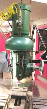
needed to mill several 1/16-in. wide slots for the steam valve ports on a
model Corliss engine. My full sized vertical mill, a Millrite, has a maximum spindle
speed of 3400 RPM, just too slow for miniature end mills. I broke a
few 1/16-in. end mills before I got the feed and depth of cut just right. It
was very-very slow and 0.015 deep per pass. Also, I had absolutely
no tactile feedback in the handwheel to indicate how the cut was progressing.
Eventually warm grease started spitting out of the spindle bearings due to the
prolonged high spindle speed.
I
needed to mill several 1/16-in. wide slots for the steam valve ports on a
model Corliss engine. My full sized vertical mill, a Millrite, has a maximum spindle
speed of 3400 RPM, just too slow for miniature end mills. I broke a
few 1/16-in. end mills before I got the feed and depth of cut just right. It
was very-very slow and 0.015 deep per pass. Also, I had absolutely
no tactile feedback in the handwheel to indicate how the cut was progressing.
Eventually warm grease started spitting out of the spindle bearings due to the
prolonged high spindle speed.
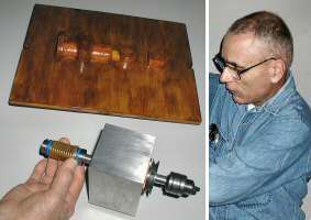
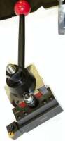
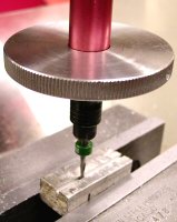
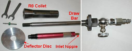
My solution was to use a micro air die grinder to drive the 1/8-in. shank of the 1/16-in dia. end mill. The grinder's body is 5/8-in and slips right into a 5/8-R8 collet. I had to make a specialized draw bar with a hole through its entire length to supply air to the grinder. The photo below shows the on-off valve and an air quick connect that were fitted to the top end of this draw bar.
Here is how it works. With the mill spindle stationary, air flows down the tubular draw bar and into the brass inlet nipple on the rear end of the grinder (see the photo below). An "O" ring seals the nipple to the hole that supplies air through the draw bar. After passing through the air turbine inside the grinder, the air is exhausted through ports surrounding the inlet nipple (rear exhaust). The exhaust air makes an immediate 180 degree turn inside the R8 collet and flows down and out through the three expansion slots in the tapered end of the collet. Notice the round aluminum disk that deflects the down drafted exhaust away from the end mill and the cut. Without this deflector, the fine chips cut by the end mill would be blow everywhere by the exhaust.
The turbine motor in the 5/8-in. dia. micro grinder doesn't have much power, but with a 1/16-in. end mill power is not a requirement; high rotational speed is, however.
|
|
|
|
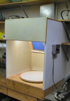
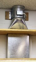
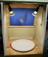
Our washing machine died last year and I saved the three sided sheet metal base that surrounded it. It is coated with a convenient light reflecting white baked-on finish, both inside and out, and serves as the surrounding containment for my bench top spray booth. The top and bottom of the booth are made from 1/2-in plywood. The booth is exhausted through 6-in. ducting via an in-duct bathroom exhaust fan (see top of middle photo) into the attic crawl space above my shop. The attic is well ventilated. I used rectangular duct since the exhaust duct had to pass up and though two rows of shelving attached to the wall. It was easier to cut a rectangular than a round opening in the shelves without having to remove them. Also, rectangular duct leaves more useable shelf space compared to the round style. Above the top shelf, the exhaust transitions into conventional round duct and then on to the exhaust fan.
At the top of the booth's open front is a hinged flip-down partial cover that shields the operators view from the glare of the built-in spot lamps (see left and right hand photos). At the rear is a spun fiber glass replaceable filter, held in a wooden frame, that removes the wet components of the over-spray before exhausting the vaporized propellant into the attic. A turntable rides on a 'Lazy-Susan' bearing so that the work can be positioned by manually rotation during spraying. Electrical controls are attached at the right, on the outside of the booth. A toggle switch operates the lamps, while a crank up 1-hour timer automatically shuts off the fan when the booth is left unattended. An air regulator (not visible) is attached to supply piping in the wall nearby that powers an air brush.
New - Old Airplane Bolts
by Joe Williams - HMSC Member
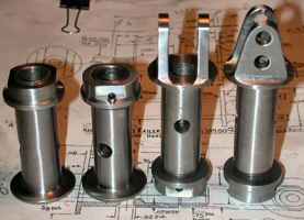 The
four bolts in the left hand photo were specifically machined for a WWI
British SE5 airplane. They are made from 4130 steel bar stock 1-1/4-in. in diameter.
The body is finished at 3/4-in.dia. and has a 1/2-in. hole drilled thru the
center except where a cross hole is drilled. The ends are threaded for a nut
that is drilled for a cotter pin. The drilling of the cotter pin holes required
a threaded stub arbor to hold the nut in a collet block during the drilling.
The information on the threads was finally located in the manual prepared by
Tom Moore and listed the thread as being a British Bicycle thread of
11/16-in. 26 tpi. This information presented was a starting place to measure
the threads using thread wires, then things changed as the tables and charts
with my thread wires had no information for a 26 tpi thread, so back to the
books, for the formulas to calculate the wire size. The calculated 'best wire
diameter' was not in my set of wires so I looked up another set of precision
wires and it contained the right diameter. From that point on it was easy to
machine the threads on the OD to the wire size and then bore the threads in
the nut to fit the bolts. The flanges required a radius at the bottom of the
cut out section and I manually ground the radius on the end of an old four flute
end mill for the job. A ball end mill did not have the correct radius. This
little project has been a good exercise in the machining art.
The
four bolts in the left hand photo were specifically machined for a WWI
British SE5 airplane. They are made from 4130 steel bar stock 1-1/4-in. in diameter.
The body is finished at 3/4-in.dia. and has a 1/2-in. hole drilled thru the
center except where a cross hole is drilled. The ends are threaded for a nut
that is drilled for a cotter pin. The drilling of the cotter pin holes required
a threaded stub arbor to hold the nut in a collet block during the drilling.
The information on the threads was finally located in the manual prepared by
Tom Moore and listed the thread as being a British Bicycle thread of
11/16-in. 26 tpi. This information presented was a starting place to measure
the threads using thread wires, then things changed as the tables and charts
with my thread wires had no information for a 26 tpi thread, so back to the
books, for the formulas to calculate the wire size. The calculated 'best wire
diameter' was not in my set of wires so I looked up another set of precision
wires and it contained the right diameter. From that point on it was easy to
machine the threads on the OD to the wire size and then bore the threads in
the nut to fit the bolts. The flanges required a radius at the bottom of the
cut out section and I manually ground the radius on the end of an old four flute
end mill for the job. A ball end mill did not have the correct radius. This
little project has been a good exercise in the machining art.
Precision
Fastening and Dowelling Tricks
by Jan Rowland -
HMSC Member
 We
all have had need to fasten two flat pieces of metal together with threaded
fasteners, with “indexable precision” ranging from the location of rusty hinges
on an old barn-door to headers on microwave apparatus. There are obviously ways
to do such with CNC gear which will facilitate repeatable centering within tenths,
but most of us A) don’t have such gear, or B) don’t have the time to program
such. But there are simple techniques anyone can do well with no more
than a drill-press. Uh, assuming the two pieces you will be fastening together
are not necessarily to be interchangeable with others.
We
all have had need to fasten two flat pieces of metal together with threaded
fasteners, with “indexable precision” ranging from the location of rusty hinges
on an old barn-door to headers on microwave apparatus. There are obviously ways
to do such with CNC gear which will facilitate repeatable centering within tenths,
but most of us A) don’t have such gear, or B) don’t have the time to program
such. But there are simple techniques anyone can do well with no more
than a drill-press. Uh, assuming the two pieces you will be fastening together
are not necessarily to be interchangeable with others.
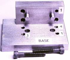
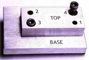
I have drilled four various partially-complete sets of holes for cap-screws in two scraps of cold-rolled just for the photos herewith. These are logically labeled “BASE” and “TOP”. The various holes are numbered for discussion below:
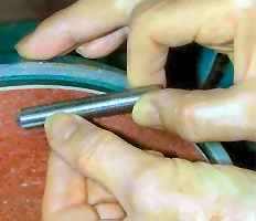
Dowelling is one possible way to insure that two flat pieces are indexed exactly, and making fine steel dowel-pins is quite easy. To chamfer a mild steel dowel-pin for use as a means to precisely locate one part against another, a lathe operation is often not necessary. By holding a length of cold-rolled as indicated in the above photo, resting on the “V-bearing” formed by your left index finger and thumb, but not holding the blank, and spinning it slowly with the right hand, you can chamfer or even point the round piece.
 If
the dowel will be used as a non-rotating pin, hold it against the top of the
disk-sander as shown, making the grind-marks parallel with the blank. If
you hold it at 9:00 (or 3:00, depending upon the direction of rotation), you
can get axial grind-marks, and with the slightest practice, you can do this
about as fine as if done in the lathe.
If
the dowel will be used as a non-rotating pin, hold it against the top of the
disk-sander as shown, making the grind-marks parallel with the blank. If
you hold it at 9:00 (or 3:00, depending upon the direction of rotation), you
can get axial grind-marks, and with the slightest practice, you can do this
about as fine as if done in the lathe.
Then, for stub-length pins, cut off these “machined” ends from the random stock with either an abrasive chop-saw, or a metal-cutting bandsaw. The length should be such that the pin can be pushed in to the first piece, to the desired depth in the second piece, about 1/16 to 3/32” deep of the surface of the first piece. Then this shallow “cup” can be MIG- or (better!) TIG welded, and ground flat with a belt-sander, etc., once cooled. The line-drawing indicates the point.
For such a fitting you will be dowelling, I suggest you might think about the need for further machining, and if practical, drill for the dowels first. I like to drill for one, insert the dowel but not weld it yet, then drill through both parts for the second, this making sure both will line up exactly, later. However, if you want to just use a few screws, no dowels, you might tack the two pieces together with SuperGlue—the pieces must of course be totally clean of oil and cutting fluid, etc. to do that. Then you can drill absolutely-mating holes, so long as the glue holds.
 I
drill the tap-pilot-holes all the way through the first part, to the desired
depth or all the way through into the second (see #1 in the line-drawing), and
then separate them. The glue, if used, can usually be loosened with a
slap on a hard surface, etc. Then you can drill-ream the body-clearance
dead-on (#2), using the pre-drilled too-small holes in the first piece for centering
the body drill. Next, separate the parts and tap the bottom piece.
Whether this will be a blind hole or through is irrelevant here. Then
counterbore (#4) if desired, or at least chamfer the holes on both sides. I
use a 60° countersink on the tapped pilot-hole ends in the BASE, to a depth
so that the O.D. of the chamfer is at least that of the screw, if not slightly
larger.
I
drill the tap-pilot-holes all the way through the first part, to the desired
depth or all the way through into the second (see #1 in the line-drawing), and
then separate them. The glue, if used, can usually be loosened with a
slap on a hard surface, etc. Then you can drill-ream the body-clearance
dead-on (#2), using the pre-drilled too-small holes in the first piece for centering
the body drill. Next, separate the parts and tap the bottom piece.
Whether this will be a blind hole or through is irrelevant here. Then
counterbore (#4) if desired, or at least chamfer the holes on both sides. I
use a 60° countersink on the tapped pilot-hole ends in the BASE, to a depth
so that the O.D. of the chamfer is at least that of the screw, if not slightly
larger.
With care, you can also use good cap-screws as fasteners and dowels by selecting a bit for drill #2 above which is exactly the same as the crest of the threads. The generally-used drills for machine-screw clearance are larger by quite a bit, to allow for sloppy fitting. So, if you want the body of the screw to fit, yet “index” the parts, you have to select smaller bits. Success with such does require a bit of experience with “just won’t go”, etc.!
|
Visit Our Home Page at |
 |
Right click below then select [Save
Target As...]
From Netscape select [Save Link As..]
Microsoft
Word version of this newsletter 290 KB