
Volume 9 , No 1- January 2004
 |
 Volume 9 , No 1- January 2004 |
|
|
|
|
|
| President - |
Vice President - |
||
| Treasurer - |
Secretary - |
||
| Webmaster - |
Editors - |
||
| Founder - |
SIG Coordinators - |
Statement of Purpose
Membership is open to all those interested in machining metal and tinkering with machines. The club provides a forum for the exchanging of ideas and information. This includes, to a large degree, education in the art of machine tools and practices. Our web site endeavors to bring into the public domain written information that the hobbyist can understand and use. This makes an organization such as this even more important.Regular Meeting

Business Meeting
Minutes are sent via email or regular mail to club members.
Presentation

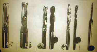
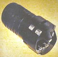
Roger Carrotte with Cutting Tools of Houston talked about deep hole drilling. He related that while drilling a deep hole on the lathe, the drill naturally follows the rotational axis when the work is turned as compared to drifting to-and-fro when the drill bit alone is turned. In addition to turning the work, rotate the bit in the opposite direction. This prevents sag of the bit due to gravity that will eventually cause the bit to drift up and to the right while drilling in the lathe. Deep drilling requires forced lubrication delivered from holes in the bit itself. The chips must be removed frequently to prevent them from being recut.
Show and Tell
|
Dennis Cranston brought the dual motor traction truck from his train locomotive |
John Hoff showed off his compressed CO2 over water rocket. |
Ed Katz brought a gemstone that he cut on his NC grinding equipment. |
|
Joe Williams brought the band saw blade brazing fixture that was featured in last month's newsletter. |
Leo Reed showed the spindle from his home made milling machine that uses a X-Y table on a drill press. |
Special Interest Groups Activity
|
|
Computer Numerical Control Sig
Charlie Mynheim showed his home brew CNC milling machine. |
Novice SigNo activity this month
Featured Articles
Solvent Can Storage Bins
by
Dick Kostelnicek - HMSC Member
|
|
|
I'm the son of a depression-raised father. I just can't throw out anything of apparent utility. So, I make my own storage bins from empty solvent cans. Yes, I know you can go to the home improvement store and buy plastic ones for a nominal price. But to me, they just wouldn't give a feeling of accomplishment.
Cut the cans with a thin 4 in. dia. friction cutoff wheel. I use an air motor to drive the wheel. You can get one from Harbor Freight for about $15. My motor is mounted on an adjustable height stand so that with the can lying on the thin side, I can cut off the side with the filler spout by manually dragging the can around its circumference against the cutoff wheel (see the second photo above).
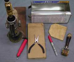 After separating the can halves, debur all around the cut and
notch and discard the seam on the four corners to a depth of 1/2 in., thereby,
allowing the four exposed edges to be folded over onto themselves. This
removes the sharpness from the top edges and provides extra strength to the
sidewalls of the bins. I use a piece of wood set inside the can to fold over
the lip by 90 degrees (see the third photo). Then, with a piece of wood backing the
outside of the partially bent edge, I bend the edge over to 180
degrees. I use a wallpaper seam roller (seen in the last photo) to flatten the
folded edges. Finally spray paint to the color of your choice.
The shallow unused can half, the one with the spout and screw lid, makes an excellent wet tray for oil sharpening stones. Just put 1/4 in. of oil in the pan, dip and flip the stone over when you want to sharpen say a wood chisel. Flip the stone again to add more oil to the stones surface for the next job.
Note the usual cautions. Cut tin is sharp. Take precautions not to get cut. Air out the cans in warm sunlight outdoors with the lids off for a day or so prior to friction cutting. A spark in a can full of flammable vapor is dangerous. I use only acetone and paint thinner cans, as the inside is clean enough to spray paint without degreasing.
Miniature Drip Oiler for a
Model Steam Engine
by Dick Kostelnicek - HMSC Member
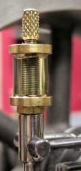
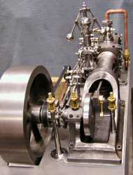 The
miniature drip oiler show in the left photo was constructed from brass bar stock
and a stainless steel threaded rod. A short length of 1/2 in. OD - 1/16 in. wall
clear vinyl tubing was used in place of the usual glass tubular oil
containment. The vinyl tube is flexible and acts as its own seal against both
the upper and lower disk caps. I used four of these oilers (one not visible)
on the Corliss steam engine shown in the right photo.
When cutting the vinyl tube, stretch it over a 3/8 in. drill rod and use a sharp cutoff blade in a lathe. This will give perfectly flat and parallel ends that will seat well against the two end caps.
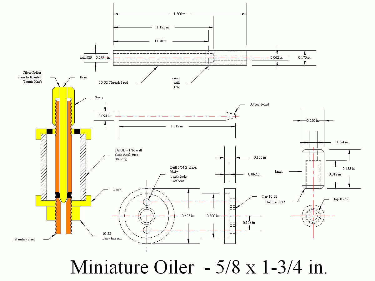
The drip rate is controlled by moving the stem of a needle valve attached to the knurled thumb screw atop of the oiler. There are two small holes in the top cover - one allows oil to be inserted while the other provides a vent during filling. Shown below is a drawing of the oiler's parts.
If you want precise working drawing, right click here,
then select [ Save
Target As...] to download a 311 KB .dfx drawing file
.
|
Visit Our Home Page at |
 |
Right click below then select [Save
Target As...]
From Netscape select [Save Link As..]
Microsoft
Word version of this newsletter 232 KB
