Volume 7, No 7 - July, 2002
 |
 Volume 7, No 7 - July, 2002 |
|
|
|
|
|
| President - |
Vice President - |
||
| Treasurer - |
Secretary - |
||
| Webmaster - |
Editors - |
||
|
|
|
SIG Coordinator - |
Membership Information
Membership is open to all those interested in machining metal and tinkering with machines. The purpose of the club is to provide a forum for the exchanging of ideas and information. This includes, to a large degree, education in the art of machine tools and practices. There is a severe shortage of written information that a beginning hobbyist can understand and use. This makes an organization such as this even more important.
Business Meeting
Minutes are sent via email or regular mail to club members.
Regular Meeting
1:00 p.m., May 11, 2002 at Collier Library, 6200 Pinemont, Houston, Texas, President Dennis Cranston presiding. There were 32 attendees, including visitor Tom Wright. Nominations/elections were held for 2002/2003 officers. Results follow:
President - Tom Moore (by acclamation)
Vice-President:- Chuck West
Treasurer
- John Hoff (voluntary second term)
Secretary - Joe Scott
Web-Master
- Dick Kostelnicek (voluntary second term)
SIG Coordinator
- (new position) Dennis Cranston volunteered
to serve as temporary special interest group coordinator pending other people
to lead the CNC. and Foundry groups.
It was decided that each special interest group would provide a presentation for the coming year.
Moving
Charles Hilton is moving to Connecticut. We hope he continues sending in his dues.
Presentation
Ball and ACME Screws as used in Home-Brew Machinery
|
|
|
|
|
|
|
|
Show and Tell
|
John Hoff showed a nice 5-C collet chuck that he made for his lathe. He also showed a slide press for a work-in-progress custom fabrications machine he is building for forming aluminum rod into fiber optic luminary holders. |
|
|
|
|
|
|
|
Metal Casting Group
We discussed Ray Etheridge's homemade ZA-12 alloying from junkyard zinc dicast, aluminum and copper. It looks like an economical way to get ZA-12. The group pour on July 6th at Zube Park (HALS- the train place) was confirmed. We'll be casting some switch components for HALS starting around 9:00 a.m. Everyone is invited to observe and comment.
From out of the Past
| Bottom It has three non-swivel casters. What is it ? |
|
Top Hint: |
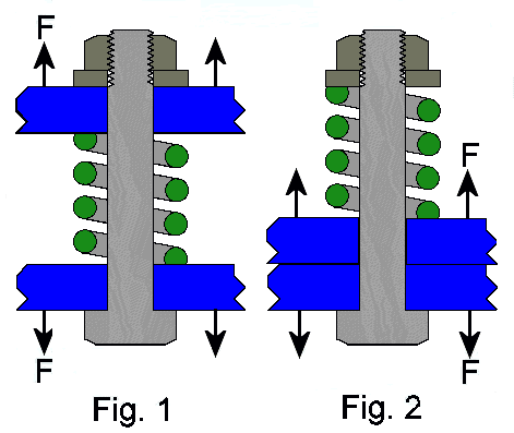 Two
plates are fastened together by a bolt, spring, washer, and nut. In both figures the
nut is torqued till the bolt tension is 2000 lbs. The spring is not
fully compressed. A force F = 1800 lbs is applied to both plates in a direction
that tends to separate them.
What is the new bolt tension in each figure? The yield strength of the bolt is 3000 lbs. Will failure occur? If a bolt yields, where will it likely occur?
If the spring represents a compliant gasket between an engine cylinder and its head, would a metal-to-metal seal be preferable?
Send your answers to webmaster@homemetalshopclub.org. We'll publish the best and the worst answers in the next newsletter
by Dick Kostelnicek - HMSC Member
Featured Articles
Foot Actuated Welder Control
by J.
R. (Joe) Williams - HMSC Member
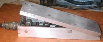 A
foot actuated control housing was fabricated from two sections of aluminum channel, 1-1/2
x 3 x 10 in. long. It uses the potentiometer from a hand
actuated control. Originally the unit was designed to be operated by thumb pressure with
the
control unit clamped to the torch handle. It didn't take long to decide
that a foot operated switch was preferable. After pricing a commercial switch
from Lincoln Electric, I decided to make my own.
The electrical connectors are type AN.
The large vertical spring is for pedal return. A 1/4 inch roller chain goes under and around a horizontal roller, and is attached to a section
of gear rack that can be seen at the lower left. When the pedal is depressed, the chain moves the rack which rotates
the control potentiometer by a small pinion gear. At the same time, a micro
switch, located at the end of the rack, initiates the welder's control
system. A small spring returns the rack to the OFF position, since
you can't push on a chain.
The foot switch can be used with stick welding where it simply turns
the power ON and OFF. For Tungsten Inert Gas or
TIG welding; it turns on the power, the high frequency starting
voltage, and the shielding gas. It could also control the cooling water
if my welding machine was so equipped. I need to add non slip material
to the housing's top and bottom surfaces, but this has worked as is for the past 14 years.
Horizontal Turning
in a Vertical Mill
by J.
R. (Joe) Williams - HMSC Member
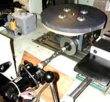 I
motorized my rotary table and bolted it to the vertical mill's table in
order to machine a 14-3/8 inch diameter x 1 inch thick PVC flange. The flange
is a special spacer for an electronic test unit. The part was too large for
my lathe and still too big for the X-Y movement on the CNC mill. The drive is
made from a small gear head motor connected to the table's input shaft
with two small universal joints and powered via a variable transformer that
feeds a diode bridge rectifier.
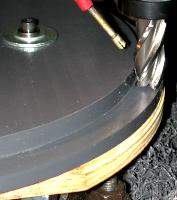 With
this setup I can mill and drill the flange provided I do things in
the right sequence. I milled the plywood's top surface before bolting the PVC
stock to the table. The plywood and PVC section were both piloted
to the center of the table and bolted in place. The work's center was located
and the mill's control system set to zero at this location. The next operation was to mill
the outer edge and the step on the flange. Then, bolt holes in the
flange were drilled and bolts installed to secure the outer section of
the flange to the plywood sub base while the inner cut out was made. This
produced a flat flange with a concentric center hole. The last step was
to turn the flange over, bolt it to the plywood and machine a radius on
the OD. Unfortunately, the drive had to be disconnected to use the rotary
table's hand wheel for spacing the bolt holes.
The table and cutter both rotate clockwise to produce infeed cutter action. With the table rotating into the cutter, there is no problem with backlash or the cutter climbing onto the work. I used an air powered spray unit with a water soluble oil solution to prevent welding of the PVC chips to the work and cutter.
The unit would be able to handle aluminum with no problem but might be a little light for steel.
Ed Note: I use this method to turn my truck's disk brake rotors with a fly
cutter since I have only a 10 in. lathe.
|
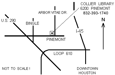
The next meeting will be held on Saturday July 13, 2002 at the Collier Library 6200 Pinemont, Houston, TX at 1:00 p.m. Bring along a work in progress to show. Visit Our Web Site |
 |
Right click below then select [Save
Target As...]
From Netscape select [Save Link As..]
Microsoft
Word version of this newsletter 296 KB
