Volume 8, No 6 - June, 2003
|
|
Volume 8, No 6 - June, 2003 |
|
|
|
|
|
| President - |
Vice President - |
||
| Treasurer - |
Secretary - |
||
| Webmaster - |
Editors - |
||
| Founder - |
SIG Coordinator - |
Statement of Purpose
Membership is open to all those interested in machining metal and tinkering with machines. The club provides a forum for the exchanging of ideas and information. This includes, to a large degree, education in the art of machine tools and practices. Our web site endeavors to bring into the public domain written information that the hobbyist can understand and use. This makes an organization such as this even more important.Regular Meeting
 Collier Library, 6200 Pinemont, Houston, Texas, May
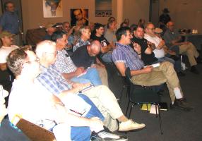
10, 2003, 1:00 pm. Tom Moore, President, presiding. There were 42 persons present,
8 of them visitors: Charlie Myhier, Dan Vincent, John Winn, John Sweigart, Dave
Pichler, Bill Dyer, Ray Stimac, and Jack Fusilie.
Collier Library, 6200 Pinemont, Houston, Texas, May
10, 2003, 1:00 pm. Tom Moore, President, presiding. There were 42 persons present,
8 of them visitors: Charlie Myhier, Dan Vincent, John Winn, John Sweigart, Dave
Pichler, Bill Dyer, Ray Stimac, and Jack Fusilie.
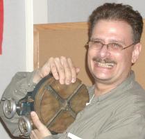
Two door prizes of two rotary tables, donated by Fred Doebbler, were won by Chuck West and John Lily.
Organization of a Novice SIG was discussed, and those interested met
after the regular meeting.
Business Meeting
Minutes are sent via email or regular mail to club members.
Presentation

Joe Scott showed a video about the National Springfield Armory established in colonial days and subsequently closed in 1975. It told of the need to establish independence from foreign gun makers and the reason that the site in Springfield, Massachusetts, was chosen. It showed the first handmade guns and then the development of machinery and gauge standards. The first machine was a wooden duplicating lathe which made gunstocks. It was invented by Blanchard in about 1820 so he could make more stocks with unskilled labor. Pay was based on piece work, and he invented about 17 different machines to increase his output. Our Blanchard grinder is his design. Gauges were developed to insure interchangeability, and they spread throughout industry. In the 1870's, Europe adopted the American System of manufacturing. The video showed making civil war muskets, trapdoors, 1903 Springfields, M-1 Garands and the M-14 rifles. In WWII, they made about 1.8 million M-1s at the rate of 5000 per day. The armoury buildings now house a college except for the central building which is a National Park Service museum.
Vincent D'Amico recalled his visits to a the The American Precision Museum located in Windsor, Vermont. Their web site has a good pictorial display of precision measuring tooling and equipment.
Tom Moore lectured on using sine bars to measure angles.
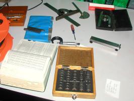
.Show and Tell
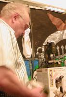
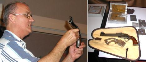
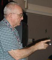
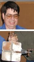
Joe Scott showed various small gun parts that he makes |
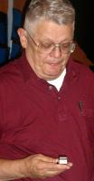
Dick Kostelnicek showed the beginnings of a Corliss steam engine that he is making. |
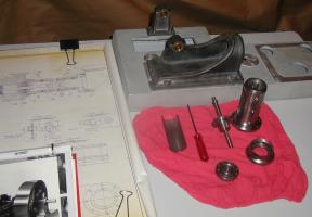
Rick Pichler showed a disc sander retaining nut he built and samples of metal Monopoly pieces he is making. |
Ed Katz showed a small 3-axis mini-mill made in Germany which can be converted to CNC. He will be a dealer for them. |
Charlie Mynheim showed a single shot pistol he made along with the molds for making the investments used to cast the various parts. |
Joe Williams showed a collet wrench with extended handle made of thin-wall conduit |
No activity this month.
Computer Numerical Control SIG
No activity this month.
Featured Articles
IN THE BUFF
Buffing Exposed
with Steven I. West
 Who
was that masked buffing man with the long moustache?
Who
was that masked buffing man with the long moustache?
Editor's Note. Steven I. West is the father of Chuck West, the club's Vice President. He presented this talk at the regular May 11, 2002 meeting.
Steven I. West, a product of the Bronx (the true home of Picante Sauce), 3rd wave D-Day in the Army Air Corps, and the Chemical Engineering Department of City College of New York, now retired, has worked in the industrial finishings, paint, and coatings industries for over 40 years. He was the head of the technical department for United Laboratories in Linden, New Jersey, and was personally responsible for 12 chemical patents including the original �Tiger� brand greaseless compound line, liquid greaseless, Tripoli, rouge, cut and color, �and other picture post cards. The products he developed have earned him international acclaim.
Steven I. West: I'll focus on the
buffing compound itself and will only briefly touch upon the equipment; buffs,
machines, speeds, accessories, etc.
I'll talk about equipment at another time.
So...
What is buffing?
Buffing, as opposed to grinding, is
removing small quantities of metal on the surface to make it even, such as
removing small pits and scratches.
And
So... What is polishing?
Polishing is the melting or fusing
of the surface through heat � the final operation in metal finishing. The finish can be a satin, scratch, mirror,
or any finish your desire.
Then...
How
do we do this?
A Few Concepts
Many products do both buffing and
polishing at once. The industry uses
the terms interchangeably.
A buffing �compound� is actually a chemical �mixture� of an abrasive suspended in a lubricant made of fats and oils or gelatin made from animal hides.
The fats and oils include animal tallow mainly from cattle, which is extracted and purified. From animal tallow comes stearic acids - a saturated fatty acid, and from petroleum lubricants such as low melting point paraffins and parafinic oils, liquid paraffin, and olifinic acids. Stearic acids are heavily used in buffing compounds. They are graded by melting points and listed as single pressed, double pressed, triple pressed and rubber grade. It is the rubber grade with the lowest melting point that is used for buffing and polishing. Hide glues come in liquid, granules or gelatin such as used in pharmaceuticals or Jello�. The hide glue is a protein as opposed to a fat or oil.
The abrasives used for ferrous or harder metals such as steels are aluminum oxides and silicon carbide. This Fused Alumna (Aluminum Oxide) is manufactured by heating alumna in a furnace until hard and brittle. It is made from bauxite or corundum, Different colors indicate different baking temperatures: red, tan, brown, gray (the hardest).
Calcined alumna is an aluminum oxide that is heated to a slightly lower temperature then that needed for fusing and is used for softer non ferrous metals such as aluminum, zinc, tin, copper, brass, silver, and gold. It is white in color. All abrasives come in different grit / particle sizes.
Compounds come in many shapes and sizes. There are liquids which are sprayed on the buffs, bars, cardboard and plastic tubes (looks like a small salami) which are hand or machine applied and pastes mainly for the automotive industry.
Which
buffing compound is for me?
For folks working in small
quantities, a bar is usually the best route.
It is held in the hand and applied to the turning buff until the surface
is evenly coated. The workpiece is then pressed against the buff until the
desired finish is obtained. It is
important to note that each manufacturer uses their own name and sometimes
their own color coding so it can get confusing what to use or what you are
using.
Hard Ferrous Metals
Heavy Duty Cutting Compounds
Greaseless � This is a mixture of fused alumna, suspended in a hide glue emulsion. Fats or oils are not used in these products, thus the term � greaseless.� The structure of the �Tiger� brand greaseless is unique (trade secret under patent) so less compound is used during the buffing operation. Grit sizes are from 50 to 400. Tiger brand Greaseless is manufactured by Matchless United in fiber or plastic tubes or a liquid.
Standard Cutting Compounds
These are composed of fused alumna suspended in fats and oils. The abrasive is manufactured in different grit sizes but generally finer than the greaseless. These come in bars or liquid and are color coded by the manufacturer for identification.
Coloring Compounds
A general term for a compound, used for both ferrous and non ferrous metals, used to bring out the natural luster in the metal through the heat of buffing. These are usually of calcined alumna suspended in fats and oils. The bar or liquid is usually light gray in color. The result in steels is a bluefish luster.
Cut and color Compounds
These are a mix of fused and calcined alumna . The intent is to perform two operations in one pass. These are widely used throughout the industry and come in both bar and liquid.
Softer Non Ferrous Metals
Tripoli � This is an oil or fat emulsion, but with an aluminum trisilicate abrasive. This very unique clay is mined naturally. It has an acicular (needle like) crystal structure. During the buffing operation needles are broken off exposing new sharp edges. Aluminum trisilicate is in three grits from the coarsest being Single Ground to Double Ground and the finest - Rose. Color is used for marketing and perfumes such as lemon oil, sassafras, and other essential oils are added. They are used widely on aluminum, aluminum die castings, brass, copper, and gold.
Rouge � This is one type of coloring compound composed of very small amounts of calcined alumna again emulsified in fats and oils. Iron oxide pigments are added of different colors for different applications.
Red Rouge � uses red iron oxide of a very fine particle size. The particles are flat plates of odd shapes which impart a reddish luster to the workpiece during the heat of buffing. This is usually in a bar.
Yellow Rouge � a calcined aluminum oxide bar colored with a yellow pigment such as a Hannsa yellow. The product is extremely alkaline and is primarily used for jewelry.
Green Rouge � is similar to the yellow but with a chrome oxide green pigment. This is also used in jewelry, silver, pewter.
What equipment do I use with this stuff?
Here are a few things to wet your
appetite and totally confuse you until the next installment, which will discuss
these items in more detail.
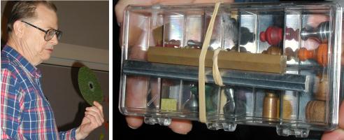
The Buff. Buffs come in as many variations as buffing compounds do. Materials range from cotton flannel to hard felt to very hard and abrasive woven sisal. They are stitched, some are pleated to dissipate heat such as an airway buff. Some are loose and held in place by the mandrel on the machine. Sizes vary from fractions of an inch to 22 inches in diameter and perhaps even larger in certain applications. Some have removable metal centers to adapt to any arbor size. Buffs are usually thin and stacked on the arbor for the specific application. Stitching varies in cotton buffs from spiral to numbers of concentric stitching at specific distances. It is the buff that does the actual work of buffing with the assistance of abrasives and lubricants of the buffing compound to achieve the final finish. There are also flap wheels, belts, bobs, and sheets
Jackson Lea is the largest buff manufacturer in this country and can be accessed on the web.
The buffing wheels must be raked to clean them when they build up too much material (metal). See http://www.mcmaster.com/ page 248.
I�m totally confused�how do I know what
to use?
You will only know what to use by asking a professional and by experimenting yourself. Since the work done as a hobby is performed by hand, pressure is huge
variable, and the equipment available
is limited. There is a
manufacturer�s representative near Fort Worth Texas that can help you with selections and purchase of
the materials and equipment. Buff,
Polish and Grind in Argyle, TX has an informative website.
Happy Buffing!
Cutting Tool Offset Indicator
by
Dick Kostelnicek - HMSC Member
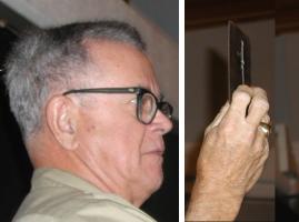
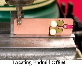
 Here
is a device that can help you locate the cutting edge of an end mill or
single point tool bit relative to the work. When an electrical circuit is completed
between the cutter's edge and the workpiece via the machine tool's frame and
this circuit board card, a LED (light emitting diode) illuminates. At that instance,
the cutter-to-work offset
is precisely determined. The indicator is useful for cutter
setup in both the lathe and mill.
Here
is a device that can help you locate the cutting edge of an end mill or
single point tool bit relative to the work. When an electrical circuit is completed
between the cutter's edge and the workpiece via the machine tool's frame and
this circuit board card, a LED (light emitting diode) illuminates. At that instance,
the cutter-to-work offset
is precisely determined. The indicator is useful for cutter
setup in both the lathe and mill.
When the copper plating on one side of the circuit board touches the work and the other side contacts cutter's edge the lamp turns on. To determine the cutter-to-work offset just add (or subtract as appropriate) the boards thickness (0.064-in my case) to the DRO (digital read out) or feed screw collar indication. The variation in my circuit board's thickness is less than half a thousand inch over its entire surface, and that's for a board right out of the scrap pile.
 Since
the circuit board is copper plated on both sides, there is little
chance of damaging the cutter's sharp edge upon contact. Even when you
crash a sharp tool edge into the card, the soft copper yields, while
the indentation left on it is no big
problem. There will still be plenty of undamaged card surface to use for subsequent measurements.
Since
the circuit board is copper plated on both sides, there is little
chance of damaging the cutter's sharp edge upon contact. Even when you
crash a sharp tool edge into the card, the soft copper yields, while
the indentation left on it is no big
problem. There will still be plenty of undamaged card surface to use for subsequent measurements.
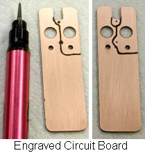
Here is how I made my circuit card offset indicator. The electrical circuits are made by using a 1/8-in. air die grinder. The mini-burr bit was used to engrave, and hence remove, the copper between areas of the card plating that should be electrically isolated from one another. The through holes for wires and also the large holes that contain the hearing-aid batteries are countersunk to provide a copper free clearance ring around each hole.
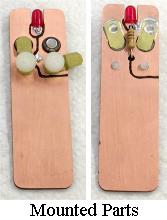 Brass shim stock was
used to form the battery retaining clips. The clips on one side are soldered
directly to the board's copper surface through a solder hole in the end
of the clip. On the other side
of the board, the clips are held in contact with the board's copper surface with #6
nylon thumb screws (available at Home Depot). The screws allow the clips to swing aside for battery replacement. You really don't
need insulating thumb screws if you remove the copper from around the threaded
hole as it emerges on the reverse side of the board.
Brass shim stock was
used to form the battery retaining clips. The clips on one side are soldered
directly to the board's copper surface through a solder hole in the end
of the clip. On the other side
of the board, the clips are held in contact with the board's copper surface with #6
nylon thumb screws (available at Home Depot). The screws allow the clips to swing aside for battery replacement. You really don't
need insulating thumb screws if you remove the copper from around the threaded
hole as it emerges on the reverse side of the board.
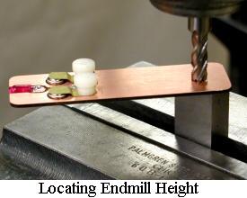
I recommend rounding the card's edge all around. I used a disk sander to do that. That way, the lamp won't light when the card edge rests on a metal surface such as the mill vise jaw; refer to the photo labeled "Locating Endmill Offset".
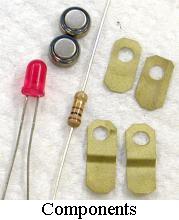
The resistor is any value between 100 and 470 ohms. Use any LED that does not have internal voltage dropping circuitry (such as one that runs on 12 volts). You'll need two 1.5 volt cells in series. One just won't exceed the LED's junction forward voltage drop. Now, don't worry about getting the connection to the LED right. Just solder it to both sides of the board. Later, if the lamp won't light, flip over the cells in their holders.
A word of caution: Be careful not to just throw the device in with a bunch of metal tools or lay it on a conductive surface, especially if you used metal thumb screws. If the circuit is inadvertently completed, the batteries will prematurely wear down.
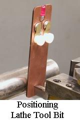
When used to position a single point lathe tool bit, the
card will be exactly vertical only if the cutter's edge is right
on center. If it leans to or fro, adjust the bit's height in order
to get back on center. Finally, for those sight challenged machinists,
replace the LED with a miniature piezo buzzer.
|
The next meeting will be held on Saturday June 14, 2003 at the Collier Library 6200 Pinemont, Houston, TX at 1:00 p.m. Bring along a work in progress to show. Visit Our Web Site |
 |
Right click below then select [Save
Target As...]
From Netscape select [Save Link As..]
Microsoft
Word version of this newsletter 276 KB