Journal of the Home Metal Shop Club of
Houston, Texas
See back page for meeting information.
President - John Korman, V. Pres.- Bill Sperry, Treasurer - Alan
May
Secretary - J.D. Wise, Editor - George Carlson , Email
geotek@wt.net
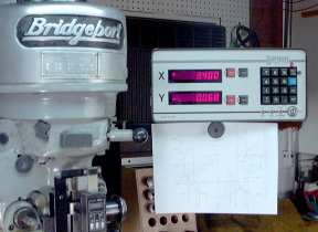
In the last newsletter I discussed the tooling you may want to acquire when you first get your milling machine. One device that can really do a lot to improve productivity and enjoyment of your mill is a Digital Read-Out System.
A digital Read-Out continuously displays the position of the milling table in X and Y coordinates. Some DROs are also capable of showing the "Z" position of the knee or quill. The display on the read-out typically uses a red or green LED numbers. The resolution of the display is 0.001" or better. Most displays are capable of 0.0005", or 0.01mm.
Advantages of using a digital read-out
The primary advantage of using a DRO is that the measurements scales, used by the DRO, measure the position of the table directly. Since the measurement is direct, and the lead-screws are not used, effects of back-lash and lead-screw wear do not cause errors in measurement. If you have a mill with worn lead-screws, you may find that it is much cheaper to install a DRO than replace the lead-screws and nuts. The DRO will also allow you to work in metric as easy as imperial. Finally the obvious, no more counting turns and setting dials. Setting zero is as easy as pushing a button.
Types of scales
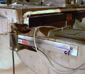
The scale is the device that encodes the position of the table. There are several different technologies used. Examples of types are capacitive, magnetic, rack and pinion with encoder, and optical. The optical are most common. In the optical scales, a long narrow piece of glass has a scale made by coating the glass with a very thin layer of chrome, and photo-etching a series of lines through the chrome. An encoder head, with LEDs and photo-transistors, is moved along the scale. Since glass has a low rate of thermal expansion, this method can give very precise operation.
Scales can vary in thickness as well. Older scales were large and had to be mounted on the front of the table. This could cause problems with the auto-stop feature of the table motor. Many newer scale are scarcely 1/2" thick. This allows mounting behind the table and out of the way. All scale technologies are pretty good, be sue to choose your DRO by looking at the whole system, not just the scales.
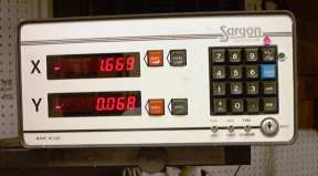
Read-out Displays
There are three levels of read-out devices available from most DRO manufacturers. Pick a readout that fits your needs and budget.
Level-One This is a readout the provides only a single counter for each axis. A reset button is provided for each axis and is used when setting the zero datum point.
Level-Two This type of readout operates in at least two modes, absolute and incremental. This means that there are actually at least two counters provided for each axis. The absolute mode is used to set the primary datum zero. The incremental mode is used to do work based upon a temporary zero at some place on the workpiece. For instance, a bolt circle may have to be drilled centered at some location on a plate. The operator would use absolute mode for finding the center of the bolt circle, then switch to incremental mode, zero the counters, and dial-out the bolt circle based on X-Y coordinates. After the holes are drilled, he places the DRO back into absolute mode and continues to the next machining operation. The absolute coordinates are not affected when the incremental counters are set to zero.
Level-Three This display unit has all the features of the level-two unit, plus, the ability to preset the counters. This simplifies working with large objects where the 0,0 datum cannot be reached to reset the counters. Instead a hole or line intersection is located and the counters are preset to this location. This type of display will also allow the setting of tool diameters for automatically generating the offsets. I prefer to use a calculator for this purpose.
In my opinion, avoid level-one readouts. Repetitive re-zeroing the main counter in the middle of the work can cause accumulated error. Level-two is the way to go for 98% of most of the work done. Buy a level three DRO if you foresee machining large panels.
Using a DRO will change the way you approach a milling machine project. Bolt circles and placing hole patterns at strange angles are now done with the DRO and a calculator, not the rotary table. A few examples of how a DRO is used are shown below.
Using a DRO will change the way you approach machining problems. Working from the center of an object rather than an edge will become commonplace. Instead of detailing the locations every object, step and repeat will make machining faster and easier. Your machining quality and confidence will soar to new heights. And even a forty-year-old mill will produce all the accuracy of a much newer machine.
By George King
This is the first part of a multi-part article on rifling in the lathe. Download the Drawing Rifling.jpg and print it out before reading this article.
The tool has two parts. Part one, a frame for holding the cutting tool is mounted to the saddle. The cutting tool is rotated by a rack and pinion mechanism, with the pinion gear attached to the rod that holds the cutting tool. Part two, the rack for the pinion gear is bolted to the cross slide.
Most Lathes have two tapped holes on the tail end of the saddle for mounting a follower rest. You will need to drill and tap comparable holes on the head side of the saddle to mount the frames. Use spacers if necessary to insure that the cross slide can clear the frames. I did not show my braces
between the upper sides of the frames because the drawings are already muddled enough.
There are two independently rotating assemblies that are only connected by the index pin. The inner assembly consists of a 3/8" rod, the index arm with it's hub, and the rifling rod connector. Set screws secure them together.
The outer assembly consists of the pinion gear, quill shaft and the index plate, all of which are a free fit on the 5/16" rod. A set screw holds the gear hub to the quill shaft, and the index plate is keyed to the latter. The index plate is drilled with holes appropriate for the number of grooves you anticipate rifling.
The rack is mounted on the cross slide in any manner that meshes it with the pinion gear. I used a 12 tooth 24 D.P. spur gear and matching rack.
In use, the cross slide nut is removed and the long taper attachment is connected. It's sine bar is set to produce the desired twist. The rifling rod is screwed into the connector and clamped. After each cut the index pin is moved to the next position. If the head spindle hole is large enough for the barrel blank, it can be held in a clamped chuck. Mine is only 3/4", so I use two center rests jammed to the tail end of the lathe with most of the barrel extending beyond the lathe.
The index arm and connector could be from one piece. My design was based on available materials. Next month - the rifling cutter.
