Volume 5, Number 3
March 2000
Journal of the Home Metal Shop
Club of Houston
President - Keith Mitchell, V. Pres.- John Lilly, Treasurer - Gordon
Lawson, Secretary - Dean Eicher Editor - Keith Mitchell: Email kmitchl@wt.net
Membership is open to all those interested in machining metal and tinkering
with machines. The purpose of the club is to provide a forum for the exchanging
of ideas and information. This includes, to a large degree, education in
the art of machine tools and practices. There is a severe shortage of written
information that a beginning hobbyist can use. This makes an organization
such as this even more important. For membership information and forms,
call or e-mail Keith Mitchell at the phone numbers shown at above.
Notes from the President
By: Keith Mitchell
The next meeting will be held in conjunction with the FIRST robotics
regional competition. For those who missed the last meeting, this is a
group of high school students who design and build robots from a kit of
parts. They then have competitions to see whose robot can best perform
certain task. Representatives spoke at the last club meeting enlisting
our support for the regional competition. The competition is held March
16-18 at the Astro Arena. Several members have volunteered to help with
this event. If you would like to volunteer please contact John Lilly. Rutland
Tool has agreed to loan a demo Jet 9X20 lathe to be operated by our members
during the competition.
I have attached an info sheet so everyone can find us at the Astroarena.
There is a meeting room reserved for us. We have a tour of the pit area
scheduled for 11:30. If you would like to tour the pit area please plan
to be there a little before 11:30. The pit tour will be followed by a short
Chips meeting. The finals of the competition start at 1:00.
The subject of remote members came up in the February meeting. Remote
members are defined as those who have a desire to participate in our club
but are not within commuting distance of Houston. I get several e-mails
each month from people all over the US and some international who want
to join our group. When this issue had been brought up in the past the
position was that we post essentially everything we do to the website where
it is free. Therefore, the only benefit to a paid membership is receiving
the newsletter by mail and the opportunity to participate in club activities.
No resolution was reached in the meeting. I propose that we appoint a committee
to study the aspects of this issue and report back to the members with
a proposal. The proposal will then be put before the members for discussion
and a vote.
March Business Meeting Agenda Since we are meeting in conjunction with
the FIRST Robotics competition, I recommend we bypass the business meeting
for March. If there are items which need to be addressed, please let advise
John Lilly at jhlilly@aol.com
February Meeting Minutes
By: Dean Eicher
Chips Meeting - 1:00 P.M. February 19, 2000, Collier Library Attendance
- 37, Three first time attendees In the Chips Meeting, the following activities
took place.
1. Lucia Sevcik - told us about the robotics competition at the Astroarena
March 16-18..She was trying to recruit people with mechanical and machining
skills to help with the competitions. For more information, check www.usfirst.org
2. Newsletter Articles - Joe Williams volunteered to write a newsletter
article for the March issue, Dominic Mancuso for April, Bill Sperry for
May, and Vance Burns for June..
3. Remote Members - Further discussions on remote members ranged from
discontinuing them to encouraging them. Proposals to both increase and
reduce dues for remote members were submitted. It was generally agreed
that remote members could provide useful information, had the same mailing
expense burden as local members, but missed the benefits of the monthly
meeting.
4. Meeting Time - Further discussions on the meeting time resulted in
no action being taken. Doug Blodgett strongly urged us to consider changing
it to avoid a conflict with the locomotive club run day.
5. Feature Presentation - Tom Moore talked about screw threads and thread
cutting. He mentioned British Standard Fine (BSF), Whitworth (BSW), and
Association (BA), Original Swiss (Thury), Model Engineer (ME), British
Standard Cycle (BSCycle), Unified National Fine (UNF), Coarse (UNC), Extra
Fine (UNEF), Special (UNS), Miniature (UNM), ISO Fine (ISOF), Coarse (ISOC),
Miniature (ISOM), ISO next choices (ISO2,3,etc.), just ISO (ISO), Metric,
Metric Miniature, Progress Watch, Swiss Watch, Acme, Stub Acme, Standard
Thread Insert (Helicoil), National Pipe Tapered (NPT), British Standard
Tapered Pipe (BSP.Tr), and Model Engineer Pipe Thread (MEPT). Tom compiled
a composite list of screw thread dimensions for the above thread series
which included single depth of thread dimensions for both sharp pointed
and form tools, feeding at both 90( and 1/2 the thread angle, for both
internal and external threads! He also mentioned the 'Root-Flat' method
and 'Crest-Flat' methods for screwcutting improved threads when a properly
radiused cutting form tool is not available.
6. George King - brought a holder he made for a conventional pencil
that attaches to a compass.
7. Dick Kostelnicek - brought a split cam for a steam engine that he
machined while it was fastened to a boring head. The straight shank of
the boring head was chucked up in the lathe and the cam offset was simply
dialed in on the boring head.
8. Joe Williams - brought some 5C collet holders.
9. Bob Lang - brought a small Rudy Kouhoupt design steam engine that
he made and ran off a tank of compressed air.
10. Doug Blodgett - brought machined castings for a steam engine blow-down
valve.
11. Tom Moore - brought a commercial between centers type boring bar.
Foundry Group Notes
By Keith Mitchell
Art Voltz presented his results from searching for Petrobond. Budget
Casting Supply seems to be the best source. They advertise both premix
Petrobond and a Petrobond kit which contains, the Petrobond resin, catalyst,
and oil. The Petrobond kit makes most sense for us since shipping the premix
is expensive and there are multiple sources for graded sand in Houston.
The Budget Casting Supply website states that it has been difficult to
obtain satisfactory results with the Petrobond kits without a professional
muller. Tom Moore has a muller and has agreed to mull the materials. It
was agreed that Keith Mitchell would order the kit and obtain sand for
a trial run with the Petrobond kit.
Bill Kimbrough brought the furnace he donated to the club. Billy Hobbs
took the furnace to his shop and will investigate what needs to be done
to make it servicable. Our first pour is still scheduled for April 22.
Delta Band Saw Blade Tensioning
Knob Revision
By J.R. Williams
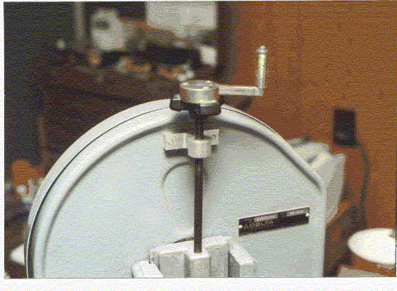 The revision
to the blade tension adjustment is a welcome addition for an "Old Man"
whose wrist joints are showing the effects of time. The crank is far easier
to turn than the original knob. The crank assembly speeds up the blade
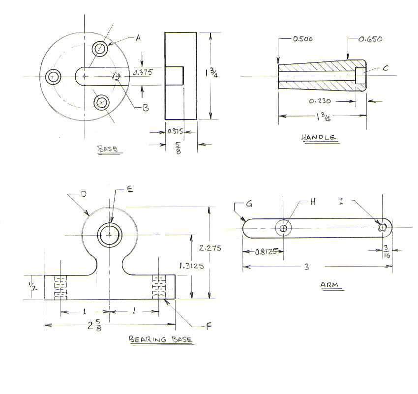
changing procedure. BASE The base unit is made from a section of brass
bar stock 1-3/4 inch in diameter with a slot for the crank arm. The slot
is cut with a 3/8 inch diameter end mill and is 3/8 inch deep. The three
holes (A) for attaching to the units knob are for 10-32 SHCS on a 1-1/4
inch diameter bolt circle. The holes are counter sunk. The other hole (B,
on the same bolt circle, is to attach the arm to the base and is drilled
and tapped for a No. 8-32 screw.
The revision
to the blade tension adjustment is a welcome addition for an "Old Man"
whose wrist joints are showing the effects of time. The crank is far easier
to turn than the original knob. The crank assembly speeds up the blade
changing procedure. BASE The base unit is made from a section of brass
bar stock 1-3/4 inch in diameter with a slot for the crank arm. The slot
is cut with a 3/8 inch diameter end mill and is 3/8 inch deep. The three
holes (A) for attaching to the units knob are for 10-32 SHCS on a 1-1/4
inch diameter bolt circle. The holes are counter sunk. The other hole (B,
on the same bolt circle, is to attach the arm to the base and is drilled
and tapped for a No. 8-32 screw.
HANDLE The handle is made from a section of plastic (or aluminum) round
stock turned to provide a tapered section 0.500 inch in diameter on the
small end and 0.650 inch diameter on the large end. The center hole is
drilled with a No. 9 drill through and counter bored (C) for the head,
5/16 inch in diameter by 0.230 deep.
ARM The arm was made from a section of 3/8 inch square brass bar stock
and is 3 inches long. The ends are machined to a 3/16 radius. The attaching
screw hole (H) is drilled to clear a No. 8-32 SHFH machine screw and counter
sunk for the head. The other hole (I) for the handle is tapped for a No.
10-32 machine screw but only 0.300 deep as the screw bottoms in the holes
threads to lock it in place on assembly.
BEARING BASE The Bearing Base is made from 3/4 inch thick aluminum stock
and is attached to the saws' upper guard with two 1/4-20 FHSH machine screws
in the holes (F). The guide section and bearing (E) consists of a 3/8 inch
bore "oilite " bronze bearing that is pressed in a 1/2 inch bore. The bearing
is 3/4 to 7/8 inches long. The outer section (D) is machined to a 9/16
inch radius and stopped in the middle to provide a 1/2 inch wide support
section.
The final assembly preparation consists of machining a relief section
in the Band Saws' knob, 1-3/4 inch diameter by 0.025 deep, using the base
as a guide to drill holes in the knob for the No. 10-32 machine screws.
The base unit is connected to the upper guard with counter sunk flat head
screws as clearance is at a premium in this area as it is adjacent to the
outer rim of the upper wheel.
Stepper Motors Need Not Be Totally
Mysterious!
By: Jan Rowland
Keith has asked me to do a kinda follow-up to the November Home-Brew
article about stepper-motor fundamentals and controls-I took that to mean
that I should compose this with an eye toward those bits of such information
which would be 1)interesting to the HMSC membership, and 2)useful to those
of us who brew our own "CNC" gear. Whew! Being academically-challenged,
that is a task! Actually, it is that which caused me to be academically-challenged
which got me on the path of self-made CNC tinkery: I am very, very lazy!
Thus, I couldn't make it in real life via conventional means, so I have
always sought ways to ease the pain of doing real work, and making machines
do mundane, repetitive jobs seemed the way to go. It has always been entertaining,
and continuously very informative; and I am most happy to do my best to
share, although I hasten with an apology to those who already know way
more than I in the following topic:
As I have said in my previous HMSC Newsletter article, there are two
routes customarily used to move those portions in CNC gear which are traditionally
moved by hand, say, by turning a handwheel, etc: "Closed Loop" and "Open
Loop". The latter method is the one which is achieved with stepper-motors,
with no feedback to the controlling computer, which would be "closing the
loop". With the Steppers, assuming all is properly engineered, this feedback
is not needed; thus, this system is considerably simpler to design and
build, and much less expensive to build, oz-in. for oz-in.
From the outside, unmounted, most steppers look exactly like any brushless
motor might. (In fact, there are Industry Standard Case-Sizes which are
common to both types). But there is a considerable difference, and I hope
to explain this sufficiently that the reader will at least have a mental
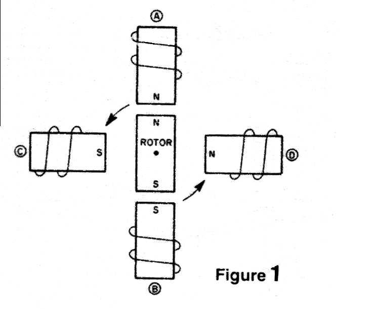
grasp of how a stepper functions: Figure 1 shows a rotor which is here
a simple bar-magnet with both "N" and "S" ends. There are four electro-magnets
about this, on 90° locations, and the polarities of the ends of those
windings are shown, assuming a particular electrical polarity to each.
You can see that the rotor is being repulsed by like magnetic-polarities
at either end, and on one side, giving the rotor no choice but to try to
move to the left, as depicted by the arrows. In Figure 2, you can see that
this has happened, and the rotor has continued on due to inertia, to an
"average" position so that its poles are centered between opposite poles
of the electromagnets.
 |
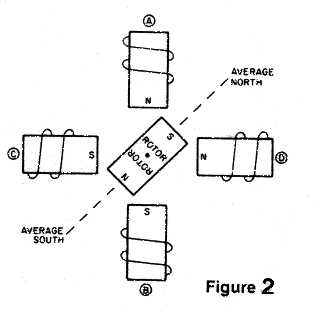 |
Now, if the electrical polarities of these windings are inverted, the
rotor will snap again, to the next position. Thus, by alternately inverting
the polarities of the windings, the rotor can be made to rotate at a constant
rate. But this rotor has, as you can see, only two possible steady-state
positions, NE-SW, or NW-SE. Not very fine resolution! But if the rotor
is made with many teeth like a pinion-gear might be, each with alternate
magnetic poles, and the windings are likewise made with teeth, but the
total number of these teeth is not exactly the same as the number of teeth
on the rotor, then, that rotor will find a point at rest where as many
teeth as possible face opposing polarities on the stator around it, and
as few as possible are not directly-facing opposing polarities. This way,
when the polarities of the stator-windings are electrically changed, the
rotor steps to the next-most-satisfactory position.
Before you stop reading in frustration, I will hasten to admit that,
no, there are not 200 different windings in a 200-step-per-turn stepper-motor!
These windings are common to groups of five teeth (I think!), and are arranged
in a parallel-series combination so that, electrically-speaking, there
are actually only two different windings, such as you have when windings
in Fig. 1 (or 2) A and B are in series, and form one winding, and C and
D are in series, forming the second winding. Thus, you have only two circuits
for motor-current. But let's go back a couple of decades in electrical
State of the Art before we go on: Refer to Fig. 3.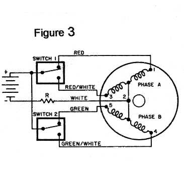 Here, you see a unipolar DC supply, that is, a single battery. The two
double-throw switches inside the heavy boxes are actually solid-state circuitry
in real life, but are so drawn here for explanatory-simplicity. You can
see that there are effectively two windings in the motor, but these are
center-tapped, and the center-taps are the (-) common, via the white wire,
through the resistor "R". Thus, when a switch is changed, the magnetic-polarity
changes in that center-tapped winding. Note, this motor has 6 leads. Also
note that only one-half of either winding is being used to carry current,
switches in either position. In other words, one-half of the copper is
unused at any time. But you have only one DC power-supply to build or buy.
Now, look at Fig. 4: Here, you have two DC supplies ("batteries" in the
schematic). But you have no center-taps, and only three wires to the motor-windings
(in real-life, both ends of both windings, a total of 4 wires, are actually
brought out to the driver-circuitry; here, the draftsman was lazy, so,
to save time, drew the concept-circuit as simple as possible for himself).
Here, you see a unipolar DC supply, that is, a single battery. The two
double-throw switches inside the heavy boxes are actually solid-state circuitry
in real life, but are so drawn here for explanatory-simplicity. You can
see that there are effectively two windings in the motor, but these are
center-tapped, and the center-taps are the (-) common, via the white wire,
through the resistor "R". Thus, when a switch is changed, the magnetic-polarity
changes in that center-tapped winding. Note, this motor has 6 leads. Also
note that only one-half of either winding is being used to carry current,
switches in either position. In other words, one-half of the copper is
unused at any time. But you have only one DC power-supply to build or buy.
Now, look at Fig. 4: Here, you have two DC supplies ("batteries" in the
schematic). But you have no center-taps, and only three wires to the motor-windings
(in real-life, both ends of both windings, a total of 4 wires, are actually
brought out to the driver-circuitry; here, the draftsman was lazy, so,
to save time, drew the concept-circuit as simple as possible for himself). 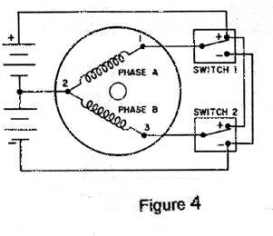 By
tracing the circuit with a pencil, you can see that a similar swapping
of magnetic-polarity of either winding happens when either switch 1 or
switch 2 is operated. Now, as you can see, all the copper is conducting
current at any instant. There is less wasted-heat, less wasted copper,
less wasted physical space, less wiring from the motor, all at the expense
of a somewhat more complex electronic driver circuit, here, shown as double-throw
switches for simplicity.
By
tracing the circuit with a pencil, you can see that a similar swapping
of magnetic-polarity of either winding happens when either switch 1 or
switch 2 is operated. Now, as you can see, all the copper is conducting
current at any instant. There is less wasted-heat, less wasted copper,
less wasted physical space, less wiring from the motor, all at the expense
of a somewhat more complex electronic driver circuit, here, shown as double-throw
switches for simplicity.
For a time, a little over twenty years back, I requested all the literature
I could get manufacturers of stepper-motors and their drivers to send me,
so long as I didn't have to pay the exorbitant postage. At first, I read
it all, cover to cover, and was arrogant enough early-on to believe I had
taught myself enough about stepper-technology to dare to build some home-brew
CNC gear. I did, and it worked. Didn't I say, before, that the reason it
did was simply that I was too stupid to realize an ignorant fool such as
I couldn't do that, so I went ahead and did, and it worked, anyway? It
can happen! Back then, driver-circuitry for size-34 and smaller stepper-motors
was simple enough that I could design better, myself, and did-and I built
my own drivers for some of the first little machines I built. Only once,
did I have opportunity to build something using size-42 and a MO-172 motor
(big as a 1-hp. 3-Ø tool-motor!), and the driver for those was a
bit too serious for me, so I bought them, ready-made. Then, just 15 years
back, those very-high-power stepper drivers were very expensive! Since
the customer was not fiscally disadvantaged, this worked OK. But lately,
I have had occasion to build two new CNC lathes, and I have decided to
beef up some parts, including the size-34 motors for the lead-screws. Fortunately,
Superior Electric, now "Motors and Motor-Controls Division of Warner/Dana",
has begun to make a new series "KM" of size-34 motors which have over twice
the torque of the old standard MO-92 motors. Those older MO-92 motors had
tapped windings for use with unipolar drivers, whereas the KML-92 motors
have untapped windings, and require bipolar drives. Oh, and the old unipolar
drives were the "R/L type", that is, in a compromise to keep the inductive
time-constant down sufficiently that the stepping-rate of those old unipolar
designs was acceptable, a power-resistor was wired in series with the +commons
to the motor-windings (center-taps). (R=Resistance, and L=Inductance) Due
to electrical-engineering details such as that might begin to imply, and
which I need not nor want to get into here, more energy is wasted as heat
from those series-resistors than the motors actually convert into useful
mechanical energy! But the new Bipolar Chopper drives chop the DC to the
motor-coils, and thereby modulate the duty-cycle, so that the average current
is no higher than the nameplate rating. But such a drive is a tad more
electrically complex, and it makes no more sense for me to design/build
my own bipolar chopper drivers than for a new-car buyer to build his own
engine in his home-shop, and buy that new car sans motor. So, for a couple
$hundred more, I buy myself more time to spend doing the mechanical work.
And, to be realistic, even if I thought I could build my own chopper drives
efficiently, the parts-cost, alone, would probably exceed the unit-price
of the ready-made/tested/warranted drives! To recap a bit: I feel it is
worth the extra money you might imagine you thus-spend to buy something
that works-for-sure, and for which you spend no time building anything
electrical.
DC Power Supply? With either the power-wasting R/L driver or the more-modern
Bipolar Chopper driver, you still have to supply amperes of current at
24 to 40 VDC for two size-34 steppers, or even two size-23 steppers such
as MO-62. Little things, only 21/4" square flange, and maybe 3" long, but
they want some amperes! A DC supply which can supply 24 VDC at, say, 8
or 10 amps, is a serious piece of electrical hardware! For stepper-motor
drivers, either kind, well-regulated DC is not particularly necessary.
In fact, I recently noted in the specs for a new drive I was perusing that
"DC Required" was "24-40 VDC". That's another advantage to the new chopper
designs: They automatically sense the average-current through their output-terminals
to the motor, and, so long as the incoming DC will supply that average
current, the chopper-drive automatically "chops" at the required duty-cycle
so that desired average current flows, with 24 VDC in , or 40 VDC. That
is, it would do you no good at all to supply regulated 24 VDC to the chopper
drivers. For the reader not "into" electronic details: A DC power-supply
can be as simple as a transformer connected to the AC line, followed by
one, two, or four diodes, and a filter-capacitor. The resulting output
would be "DC", but the actual voltage would depend upon the instantaneous
AC-line voltage into it, the load-current, the condition of the parts and
the temperature of the transformer, etc. But if you "followed" that DC
with a regulator, you could keep this DC-out within a fraction of a percent,
so long as the "raw DC-in" was at least 2 volts, or more, than the regulated
output voltage. Such details are trivial to a person into electrical stuff,
but such a detail can have a significant effect upon the reliability, actual
function, and cost-to-build of such a project as discussed here.
Warner/Dana has been introducing new stepper-drives and DC supplies
faster than the post-office has been delivering their junk-mail to me!
For the two new CNC Lathes I am building at the moment, I have ordered
and received two new units from them which contain power-supplies and two
motor-drives, each. Oh, and they have opto-isolated inputs, meaning that
they should be about as electrically-immune from EMI (electrical noise)
as practical. Electrical noise? Yes -- with circuitry involving computers
and like electronic gear, you can have "spurious inputs" from such sources
as a large machine with a nasty magnetic contactor coming on, across the
room; an AC unit with a poorly-wired AC-line-in, or even something as simple
as a Mr. Coffee machine switching to the "keep it warm" mode, in the same
room! Surely the reader has noticed those little "sparkles" on the TV-screen,
now and then, even when the lights don't blink, and there is no lightening-storm
in visible proximity? That is "electrical noise"! It can be harmless, or
it can cause several steps (0.0005" each!) into that nearly-finished arbor
you are turning, which has an OD tolerance measured in tenths!
Some further chat on that point might be of interest: The little CNC
lathe I built at home in '84 for a very esoteric and specific task, turning
pipe-organ drawknobs, has, by now, made about 18,000 knobs of "exotics"
such as ebonies and rosewoods of several kinds, and even some Continental
European Boxwood, which had been stored in an attic in England for the
last 127 years-long very illegal to harvest, transport, sell, export, mention,
or show!- In all that time, whenever I hear thunder, I switch off and go
inside and hassle the wife. Because a lightning-strike on a power-line
within miles can cause a "glitch" which can cause an unwanted step, or
stall. This latter might not "ruin" a work-piece, but then, I have to "find"
the 0,0 point again, once the lightning has gone away, and "cut air" until
the cutting-tool gets back down to where it left-off. Oh, that is very,
very rare, but it has, more than once, cause the utterance of untoward
syntax!
