Volume 10, No 5 - May 2005
|
|
Volume 10, No 5 - May 2005 |
|
|
|
|
|
| President - |
Vice President - |
||
| Treasurer - |
Secretary - |
||
| Webmaster |
Editors - |
||
| Founder - |
SIG Coordinators - |
Statement of Purpose
Membership is open to all those interested in machining metal and tinkering with machines. The club provides a forum for the exchanging of ideas and information. This includes, to a large degree, education in the art of machine tools and practices. Our web site endeavors to bring into the public domain written information that the hobbyist can understand and use. This makes an organization such as this even more important.
May Program
A few meetings ago we had a "back to school" session using Machinery's Handbook. That meeting received a mixed review. Some liked it and wanted more; others were not impressed. The May program will be similar in that it will be "back to school" again. We will take up various topics for club discussion including but not limited to:
Chip color and its relevance to tool temperature
Various coolants, their pros, cons and uses
Drill bits - split point vs. chisel point
Backlash and gib looseness and how they effect machining
Various cutters - HSS, Cobalt and Carbide, their relevance to speed,
coolant and type of material being cut.
Rotary tables and indexing plates
Angles on shop ground tooling
Adjustments during manual machining 'till it feels right" vs. rigid "by the book" adherence
to specific guidelines
Chip breaking and removal
Cut off tooling
Any other topic members bring up during the meeting
If this discussion does not produce disagreements, it will be considered a failure. Be prepared to offer your solutions and experiences.
April Regular Meeting
 Collier Library, Houston Texas, April 9, 2005, 1:00 p.m., Chuck
West - President presiding. Attending were 35 members and 5 Guests; Terry
Flanigan, Hanz Blum, Stanley White, Michael Gamber,
and Gayle Hopson, Jo M. Sylvester.
Collier Library, Houston Texas, April 9, 2005, 1:00 p.m., Chuck
West - President presiding. Attending were 35 members and 5 Guests; Terry
Flanigan, Hanz Blum, Stanley White, Michael Gamber,
and Gayle Hopson, Jo M. Sylvester.
Doug Chartier presented a difficult turning situation that he had run into
concerning cutting threads with a tungsten carbide at low RPM.
Business Meeting
Minutes are sent via email or regular mail to club members.
Presentation

Steven
clay talked about his experiences in making molds for the hot plastic injection
molding process.
Show and Tell
|
|
|
|
|
|
|
|
|
Novice Sig
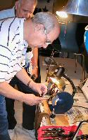 Twist
drill hand sharpening: When dull, simply replacing larger twist drills can be
expensive. Sometimes drill sharpening fixtures are not available or the larger
drills may not fit into the available fixtures. The Novice SIG was offered demos and hands-on opportunities to hand sharpen twist drills
under the direction of several of the club's experts.
Twist
drill hand sharpening: When dull, simply replacing larger twist drills can be
expensive. Sometimes drill sharpening fixtures are not available or the larger
drills may not fit into the available fixtures. The Novice SIG was offered demos and hands-on opportunities to hand sharpen twist drills
under the direction of several of the club's experts.
One Machine Tool Practices Notebook was distributed. - by Richard
Pichler
Featured Article
A
Chip Magnet from The Tinker Shop
by Bob Fournier
After 40 years in Tool & Die / Maintenance, I retired, a year ago. Everyone said, you had better have a side job or hobby, or you will die in the easy chair, in front of the TV. I have a little garage 16 by 24 ft. with a pot belly stove, that I�ve been tinkering in for years. I like to work with wood, but after you have been in the trade as long as I, you can�t get away from working with metal. I already had an 11 in. Rockwell Lathe, small band saw, drill press, and a wire welder.
At retirement, I considered selling some of my tool & die tools. What does one do with 3 tool boxes full of tools? With age one learns not to make such spur of the moment decisions. I decided to keep everything for at least a year. Thank God I made that decision. One year after retirement, I have my little Tinker Shop and can easily spend 8 � 10 hours a day in it.
We just got high speed Internet and I ran across your web site. I really enjoy all the info on your site! You asked for some articles or projects to publish. So, with your permission I will send you some.
The Chip Mag.
 I purchased a small drill-mill and after a few projects, the chip pockets filled up with
chips. In the past we just swept them out onto the floor. But in my garage
I try to keep the floors fairly clean. My wife complains if chips are found
in the house. I tried brushing chips out of these pockets directly into the
basket, some still end up on the floor and you can never get the corners completely
clean. I tried a magnet,
but you end up with a ball of needles.
I purchased a small drill-mill and after a few projects, the chip pockets filled up with
chips. In the past we just swept them out onto the floor. But in my garage
I try to keep the floors fairly clean. My wife complains if chips are found
in the house. I tried brushing chips out of these pockets directly into the
basket, some still end up on the floor and you can never get the corners completely
clean. I tried a magnet,
but you end up with a ball of needles.
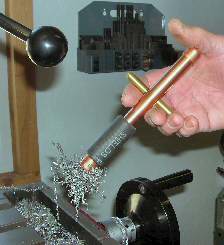
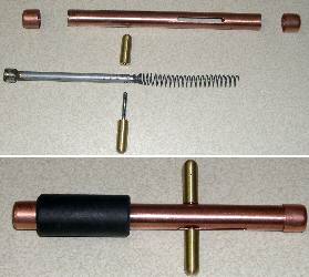
In just one day, I developed a Chip Magnet made from odds and ends and copper tubing. I had two of those little, very strong, telescoping pocket magnets; so I sacrificed one.
Cut the magnet of the thin tubing with side cutters, leaving a �-in. stub on the magnet. Drill a clearance in the end of a �-in. diameter rod 4-�-in.. long, for stub on magnet. Turn �-in. diameter on the other end of rod, for spring guide. Drill and tap 8-32 cross hold for handle. Epoxy magnet stub to �-in. Aluminum rod. Some �-in. hard copper with caps made up the barrel. The slots were milled in with a 3/16-in. end mill, undersize works well. The handles are 3/8-in. brass drilled and taped for 8-32. A long 8-32 screw was cut off, so when it was bottomed out in the brass handle, it had clearance to slide in the barrel. A light spring is needed. I stretched out an expansion spring, 0.032 wire. If you have the wire, it might be a good time to try your hand at spring winding.
On my test model I used a large rubber grommet, to keep the chips at the end, but some jumped around the grommet. This is when I went to a piece of radiator hose. The copper pipe caps are just tapped on.
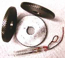
Magnetic
Lathe Face Plate
by J. R. Williams
- HMSC Member
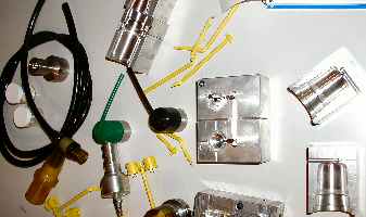
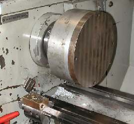 I
recently attended an auction and wound up the owner of two Zero Spindle
mechanisms. One had an 8-in. diameter magnetic chuck and the other had
a clamping arbor. I thought the units had an indexing pin and might make a good
spin index fixture, but that was not the case. Then the idea came to me
to mount the magnetic chuck on my lathe. That meant fabricating a D1-3 mount.
I remembered the Lathe Dog Drive Face Plate that came with my lathe. The
cast aluminum base for the unit was bored out to fit the OD of the face plate.
Next came modifications to the drive plate. I drilled six holes
on a uniform bolt circle and tapped three of then for jack screws and the other
three were counter bored for socket head cap screws. The cast aluminum
part was tapped for the mounting cap screws. The photo shows the unit installed
on the lathe ready for a project such as facing thin steel washers.
I
recently attended an auction and wound up the owner of two Zero Spindle
mechanisms. One had an 8-in. diameter magnetic chuck and the other had
a clamping arbor. I thought the units had an indexing pin and might make a good
spin index fixture, but that was not the case. Then the idea came to me
to mount the magnetic chuck on my lathe. That meant fabricating a D1-3 mount.
I remembered the Lathe Dog Drive Face Plate that came with my lathe. The
cast aluminum base for the unit was bored out to fit the OD of the face plate.
Next came modifications to the drive plate. I drilled six holes
on a uniform bolt circle and tapped three of then for jack screws and the other
three were counter bored for socket head cap screws. The cast aluminum
part was tapped for the mounting cap screws. The photo shows the unit installed
on the lathe ready for a project such as facing thin steel washers.
If you have a surface grinder, a magnetic lathe face
plate may
not be something you should put a lot of time or money into.
Checking Out a Junk
3-Phase Motor
by Dick Kostelnicek - HMSC Member
If you've got your eye on a cheap, used, 3-phase motor and you are on bended knees at the junk yard, there are a few simple tests you can do right there on the scrap heap. I won't dwell on mechanical checks, since you wouldn't be reading this article if you didn't have some idea of what could be wrong with a motor mechanically. You know, stuff like a cracked housing, rough bearings as you spin the rotor by hand, excessive side and end play of the shaft, etc. I want to cover, rather, electrical checks that you can make in the field. in order to determine: Overheating, Wire Identification, Leakage to Housing, Winding Identification, Winding Integrity. Leakage Between Windings
 Overheating:
After
the motor passes your mechanical inspection, consider that it
may have been junked for an electrical reason. Remove the electrical
connection access or cover plate. Don't forget to bring along several different
kinds of screwdrivers and a small vice grip to aid in
removing the cover. Most 3-phase motors are totally enclosed, so the only
place to get a good whiff of how the interior smells is through the holes
that the power wires come through in the metal housing under the access
plate. If the motor smells strongly of burned wires or its coat of paint
appears discolored from excessive heat, move on to another prospect.
Overheating:
After
the motor passes your mechanical inspection, consider that it
may have been junked for an electrical reason. Remove the electrical
connection access or cover plate. Don't forget to bring along several different
kinds of screwdrivers and a small vice grip to aid in
removing the cover. Most 3-phase motors are totally enclosed, so the only
place to get a good whiff of how the interior smells is through the holes
that the power wires come through in the metal housing under the access
plate. If the motor smells strongly of burned wires or its coat of paint
appears discolored from excessive heat, move on to another prospect.
Wire Identification: Note if there is a wiring diagram on or under the access plate or possibly on the motor's name plate. In place of a diagram, there may just be a connection list like the one seen in the lower right corner of the diagram included with this article. Also ensure that each wire has a different color or number tag as referenced in the wiring diagram or connection list. If not, I would pass up this motor because it may have been junked because it was wired wrong for lack of a diagram. Now, disconnect all the motor wires from any remnants of feed wires that came from the three 3-phase electrical power lines ( L1, L2, L3 ). Use a wire cutter/stripper in case you can't free each wire by just untwisting them. Usually, they are connected with wire nuts, so just screw them off counterclockwise. Now, you should end up with 9 separate motor wires with the insulation stripped back from their ends. Nearly all of the dual voltage ( 220 - 440 V ) 3-phase motors under 10 HP in the USA are wired in what is called a 3-wire Y-connection. There is no fourth wire connected to the electrical neutral. However, there should be a ground wire connected to the motor housing that prevents electrical shock and static electricity build up. This ground wire, however, is NOT part of the 3-phase power connection. Virtually every motor that you will encounter, has an internal floating neutral connection that is not connected to the 3-phase supply ( see the diagram ).
Leakage to Housing: Next, use your ohm meter set on its highest, most sensitive, setting and check for any leakage or continuity from each of the 9 motor wires ( see the diagram ) in turn to the motor housing. You can determine if your meter is sensitive enough by wetting your finger tip with saliva and then touching the two meter probes to the wet finger at a spacing of about a 1/4-in. You should see a noticeable deflection of the ohm meter's needle. If you are using a digital ohm meter, this should be in the range of 100K ohms. If you can't measure the resistance of a wet finger, then your meter is not sensitive enough to find high resistance leakage from the motor windings to its housing. Pass up the motor if there is the faintest hint of leakage ( measurable resistance ) to the motor's housing
Winding Identification: Now there are just 6 coil windings in your motor, regardless of its speed rating (3450, 1750, 1125 RPM). Three of these windings are connected together internally. The remaining 3 wires attach to 3 separate unconnected windings ( see the diagram ). Starting with any of the 9 wires, connect the ohm meter to it with an electrical clip in order to free both of your hands. While on the lowest resistance setting, touch each of the remaining 8 wires in turn while looking for continuity or a low resistance value ( less than a few ohms ). If you find continuity with just one other wire, it is connected to one of the 3 separate windings. Tape these two wires together a half inch or so below the place where the insulation is removed. If, on the other hand, you find that there is continuity to two other wires, tape these three together as a group. Next, clip on to any wire that is still free ( not taped into a group ) and find the other wire(s) connected to it. If you ever find continuity between 4 or more wires or simply NO continuity to another wire, discard the motor. When you're done, you should have one taped group of 3 wires and 3 taped pairs of wires. If this is not the case, discard the motor.
Winding Integrity: On the meter's lowest resistance setting. measure the resistance between the wires in each of the 3 groups that have just two wires. Note the 3 values on paper. For the single group that contains 3 wires, measure the resistance between two wires at a time. There will also be 3 readings here. Note them on paper. Now, the readings should all be the same for the 3 groups of 2 wires, about 0.5 - 3 ohms for motors between 1 - 10 HP. The three readings for the group of 3 wires should also all be the same but twice the resistance as for the readings from the 3 groups of two wires. Now, differences of 10% or less between values is OK.
Leakage Between Windings: Lastly, twist together the exposed ends of the wires in each groups. With the ohm meter set again on high, check for any leakage between two of the groups in turn. For the 4 groups there will be 6 meaningful readings here, but you may wish to measure all 12 possible combinations of the groups. There should be absolutely no electrical connection between any of the groups of wires.
If you passed all these tests, the motor is probably OK, electrically.
Tools you will need in the field: roll of tape, wire stripper/cutter, Phillips and flat blade screwdrivers, small vice grip, high and low resistance ohm meter, pencil and paper, umbrella if it is raining.
|
Visit Our Home Page at |
 |
Right
click below then select [Save Target As..]
From Netscape select [Save Link As..]
Microsoft
Word version of this newsletter 260 KB