
Presentation
Joe Scott showed a video on the history of Springfield Armory and gave an interesting talk on chambering firearms and adjusting for proper head space. He also explained the legalities of gunsmithing.
Vice President - Tom Moore
Treasurer - John Hoff
Secretay - Ed Gladkowski
Web Master - Dick Kostelnicek
Editors - Keith Mitchell, Jan Rowland, David Whittaker
This is also a good time to remind everyone that dues for the 2001-2002 year are due this month. Dues are $1 per month ($12 for the year) for existing members and $8 initiation fee for new members. Please see John Hoff to pay. Dennis Cranston
Dick Kostelnicek asked the members present if they wanted to receive
their newsletters electronically. 13 members agreed and 2 members preferred
mailed copies. Dick will have a sigh-up sheet for electronic newsletters
at the next meeting.
|
|
PresentationJoe Scott showed a video on the history of Springfield Armory and gave an interesting talk on chambering firearms and adjusting for proper head space. He also explained the legalities of gunsmithing. |
Richard Pichler showed suggested club business cards and cardholder; also a deluxe clothesline holder.
Jan Rowland showed a selection of very fine organ stops produced on his own-made CNC lathe.
Anthony Yon showed a piece of large diameter, heavy-wall aluminum tubing he successfully cut off using a carbide blade on his radial arm saw.
John Hoff showed his water-cooled heat exchanger for refrigerant liquid pre-cooling in his pursuit of energy conservation on his air conditioning system.
Visitors:
August 17, 2001
Usually, motor rotation is not reversed. Furthermore, power may be reapplied prior to full stop. However, in the special case of a single face wheel grinder, it may be necessary to both stop and reverse the direction of rotation in order to grind on the opposite end of the table rest. For example, a lathe-threading bit requires that both the left and right sides be accurately ground. By reversing a face wheel's rotation, both sides of the bit can be symmetrically ground. This work can also be accomplished without reversal by using two face wheels, one on each end of the grinder's spindle together with complimentary tilted table rests. In the case of a grinder for carbide bits, the high cost of using two resin bounded diamond face wheels gives great incentive to reversing the rotation of a single wheel. However, waiting for a free wheeling grinder to coast to a complete stop prior to each reversal may not be worth the monitory savings.
Induction motors with electrically separate start and run windings (four wire connections) can be easily reversed by flipping the connection of either winding but not of both. Ever since OSHA entered upon the scene, grinder and saw motors have been manufactured with three wire connections. In other words, one end of both the start and the run windings are connected internally and brought out as a single wire. Now, you can't just flip a winding to reverse these motors.
There are compelling reasons for not reversing the rotation. When a circular saw's rotation is reversed and the blade is flipped over, the work will cut normally but it may be violently kicked back or pulled away from the operator. Likewise, it is possible, but not safe, to grind with the wheel coming up from under the work rest. Additionally, reversing the saw or grinder rotation might cause poorly tightened arbor nuts to spin off, allowing wheel or blade to become detached from the arbor. Manufactures of intentionally reversible grinders secure their face wheels by bolting them onto a flange and keying the flange to the spindle.
Arbor nut spin off can also occur when rapid braking is applied to a motor spindle. Saws and grinders of recent manufacture often come without brakes. Rather than risk the loss of a retaining nut when breaking, the manufacture advises the tool user to wait till the motor comes to a complete stop. The operator is further cautioned not to use sticks or metal objects pressed against the wheel or blade in an effort to bring the motor to a more rapid stop. A typical six inch grinder takes 85 sec. while a ten inch table saw takes 100 sec. to free wheel to a complete stop.
The purpose of this article is threefold:
This time changing unidirectional stator magnetic field can be thought of as being composed of two counter rotating magnetic fields. At 60 HZ, the rotation speeds are 3600 RPM right and left. Now put yourself on the turning rotor. The field that rotates in the same direction that you are turning appears to be rotating slower that the one going in the opposite direction. At full speed, 3450 RPM, the rotor sees two magnetic fields rotating in opposite directions, 150 RPM and 7050 RPM. The rotor voltages induced by these two fields are at 2.5 HZ and 117.5 HZ respectively. Note: Divide speed in RPM by 60 to obtain frequency in HZ. The self-inductance of the rotor inhibits the flow of current from the high frequency induced voltage. Only the current induced by the 2.5 HZ or 150 RPM relative (slip) speed supplies sufficient torque to keep the motor turning.
Even if the start and run windings are not separate (three wire connection), the initial rotor torque can still be reversed electrically. Rather than employing a start capacitor, an inductor is used in its place. This inductor must be large enough to shift the start winding current in the opposite or lagging phase direction. However, the additional inductance must not be so large as to impede current flow in the start winding, which already has its own large inductance. Hence, a trial and error method is appropriate. I found that the 24V secondary winding on a 110V - 24V Radio Shack transformer had just the right inductance for reversing a 1/2 HP 3450 RMP grinder. The starting torque is about 1/3 that produced when a start capacitor is used. Consequently, it takes longer to come up to final speed in the reverse direction.
Figure 2 shows the reversing circuit diagram that employs a DPDT-Center-Off power switch. When up to speed, and the switch is flipped directly from forward to reverse without allowing the motor to come to a stop, the motor just continues to run in the same direction. Only when the motor has slowed sufficiently and will draw additional run current, will the start relay pull in and produce reverse motor torque. I use a special DPDT switch that can't be thrown from forward to reverse without first pausing at center off. The addition inductor (transformer secondary winding) and DPDT switch fit with plenty of room to spare in the pedestal base of my far-East-knock-off of a Baldor carbide grinder.
A note on current starting relays. These devices may be very sensitive
to gravity. In order to sense a current change at high amperage, these
relays have just a few turns of thick copper wire in their coil. Therefore,
they need a very weak spring to balance the weak magnet force generated.
With cheap designs, gravity provides just such a weak spring. In my grinder
the relay was initially mounted at about a 75-degree slope. I had to remount
the relay vertically in order to ensure relay dropout at a larger run winding
current when the motor used the inductor for starting. Aligning the relay
with gravity increases the effective restoring force. Alternatively, removing
a few turns from the relay's coil will force it to drop out at a larger
run winding current.
How much DC is necessary to stop a 3450-RPM grinder in a just few seconds?
Well, my solution uses a 12V-lawn tractor battery that can easily supply
12 amps for several seconds to the 1.0-ohm run winding resistance. Table
1 shows the stopping times for various 12V battery powered dynamic braking
applications that I have constructed and used. You'll have to recharge
the battery, so an inexpensive trickle charger is appropriate here.
| Application |
|
|
|
|
|
|
| 6" - 110V Grinder |
|
|
| 10" - 110V Table Saw |
|
|
| 12" - 220V Radial Arm Saw |
|
|
Figure 5 shows component location in the grinder's pedestal base. The
reversing inductor is at the left, and start relay is at the right. The
start capacitor can't be seen as it is buried below the mass of wires in
the center. The battery cable exits the pedestal at the bottom left through
a rubber strain relief. The two operating switches are at the center top.
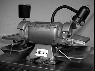
Figure 4. Finished carbide grinder. |
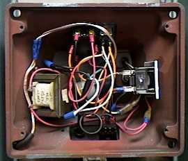
Figure 5. Inside the grinder pedestal. |
