President - Keith Mitchell, V. Pres.- John Lilly, Treasurer - Gordon Lawson, Secretary - Dean Eicher, Newsletter Editor - Keith Mitchell Hm (281) 391-2406 Wk (713) 215-8123 Email kmitchl@wt.net
Membership Information Membership is open to all those interested in machining metal and tinkering with machines. The purpose of the club is to provide a forum for the exchanging of ideas and information. This includes, to a large degree, education in the art of machine tools and practices. There is a severe shortage of written information that a beginning hobbyist can use. This makes an organization such as this even more important. For membership information and forms, call Keith Mitchell.
At the August meeting we had eight first time attendees. It's really great to see that many new people join our group. I want to welcome all of you. If one more person had shown up we would have been in the standing room only mode. We need to be looking for another place to meet. The library has met our needs (free and convenient) until now. If you have any ideas please let me or one of the other officers know. Better yet, attend the next business meeting and let's discuss your idea.
A lot of the club communication is done by e-mail so if you have an e-mail address and would like to be in the loop, please e-mail Gordon Lawson at Gordon.lawson@uk.akzonobel.com. He will update the master list. It was pointed out at the last meeting that we don't have much written down to introduce new members to the resources of the club. We need a "Club Directory" to make new members aware of the items in the library, perhaps an index to the articles on the web site, club charter, the supplier's list Bill Sperry is compiling, etc. I'll be looking for recruits for this project. Speaking of suppliers list, please help us all by submitting your sources for materials, supplies, model kits, tools, and machinery to Bill.
This month's newsletter contains two excellent articles. John Lilly produced the article on adapting a knee power feed to a mill and from J.D. Wise we have the second installment of a three part article on lapping. In coming issues Jan Rowland has prepared an article on CNC for the November Newsletter and has done a supplement on stepper motor fundamentals. Joe Williams has done an article on the hand tapper he brought to the July meeting.
In September we collect dues for the coming year. Dues are $8.00 initiation fee and $1 per month thereafter. Our biggest recurring expenditures are the newsletter and the website. We have slightly more than 50 members so we collect approximately $600 per year. Were it not for some donated services the newsletter would cost approximately $1.00 per copy. Currently dues are our only source of income. Some of the people who joined in mid year this past year over paid. Our treasurer, Gordon Lawson, has calculated the credit to carry over against this year's dues. Please get with Gordon Lawson to pay your dues. We would like to have everyone do this without being reminded again. If you have any questions regarding the treasury contact Gordon.
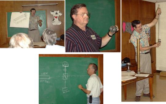
I would like to thank John Hoff for his super presentation on lathe reconditioning. Everyone who attended the August meeting now has a better idea of how to inspect and recondition used equipment. The September presentation will be by George Carlson on "Setting up the Perfect Shop". George will cover equipment selection and shop layout. For the October meeting program be thinking about something you make in the shop which would make a good Christmas gift. The November program will be by Ron Blair on applying three-phase variable speed drives. I would like for everyone to think about a presentation they might give. We try to set these up well in advance to allow plenty of time to prepare.
I've been working on an article about how our club was started with the idea that it may provide some help to others who may want to start something similar. The first meeting was held in May of 1996. At the September meeting I would like to try to get everyone who attended the May 1996 meeting together for a group picture. If you were at the May 1996 meeting please make the effort to attend the September meeting. See you the 18th.
Chips Meeting - 1:00 P.M. August 21, 1999, Oak Forrest Library Attendance - 39, Eight first time attendees In the Chips Meeting the following activities took place.
1. Supplier List - George Edwards has a list of suppliers and a notebook full of pictures of materials available from several of the suppliers.
2. Photographing Exhibits - Both George Carlson and George Edwards have digital cameras that they will try to bring to meetings and photograph presentation items and exhibits.
3. Swap Meet - Our next swap meet will be at the Rutland Tool parking lot at 7:30 A.M. October 9, 1999.
4. Feature presentation - John Hoff talked about purchasing used machine tools from auction sales and dealers. He described several things to look for in choosing a lathe for purchase. John then told us about his purchase of a Dean Smith and Grace lathe that had a worn spot in the bed near the head stock, and about his method of fastening reference bars to the bed for use as guide rails for a bed grinder he made. Also, John told us about putting liner strips in the worn out v-groves in the saddle and hand scraping them for a proper fit.
5. John Hoff - showed the major parts to a sucker rod type water pump he was making for a geothermal air-conditioning condenser.
6. George Edwards - showed a small four jaw chuck that he simply chucks in his large three jaw chuck when he is working with small material.
7. Mike Hancock - drew a diagram of a laser interferometer which could be used for precision measurement of level surfaces.
Doing frequent setup changes on the milling machine caused a lot of work
moving the knee up and down especially when changing form using a vise to using
a horizontally mounted rotary table. This trouble was exaggerated by the fact
that the outer sleeve of the drive handle assembly was cracked at the broaching
for the key-way. This made it very difficult to raise the table with a load on
it. Some type of repair had to be made. Luckily, I bought a power feed at an
auction. The power feed was missing the final drive gear. I called Grizzly's
service department and was able to get a gear to fit the manual feed shaft for
$27.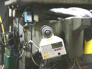
Next, I did the most necessary step to complete any project of this nature. While removing the old sleeve assembly I managed to completely crack the old assembly. This made it an absolute necessity to finish the project. Unfortunately this is generally the way most things get accomplished in my shop.
At first I tried to mount the power feed horizontally with the controls on top. This did not work because of an interference problem with the X-axis limit switches. Next, I tried to mount the power feed vertically. This did not work because the screw holes already in the machine would be too close to the new location to allow for tapping the new holes with out doing some major standard repair procedures (making some cast iron screws and locktighting into the old threads). So I settled for mounting the assembly slightly off vertical.
The new gear had been broached for a keyway already. The old keyway was not usable and a new one had to be machined to size. I would normally do this operation on a milling machine. Since my machine was no longer functional I resorted to the tried and true third world machining technique of filling the part to fit. The keyway prevents the drive gear from rotating on the shaft. I used a 3/16" roll pin to prevent the gear from being pushed forward on the shaft by the drive gears. The hole for the pin had to be field machined. After inserting the pin it was cut to length and filed flush with the top of the gear.
I bored a fender washer for use as a spacer between the gear and the indicator dial. I put the assembly together and used a feeler gage to determine how much too wide the gap was between the power feed body and the indicator dial. I made a recess cut in the fender washer to reduce the gap to 0.005".
I tested the drive mechanism and found that there was enough control to position the table within 0.0005" every time. I did not make a manual drive hand wheel as I had originally intended.
I mounted the limit switch assembly with the switch portion on the knee. This decision resulted in the necessity of reversing the position of the top and bottom limit switches inside the one-piece assembly. I mounted the stops on a track so that they could be adjusted later.
The power feed had plenty of power to lift the table with a 300 lb. Load. This would be a good project for any shop that does frequent setup changes on medium to large size machines.
3. Flat Lapping
Let's suppose that our goal is to produce a flat, smooth surface on a piece of (possibly hardened) steel. For convenience, assume that it is already "almost flat." Suppose further that we have a reference surface (e.g. a surface plate) that is "flat enough."
We could transfer the flatness of the reference indirectly by scraping: high spots are marked by a layer of dye on the surface plate and removed by the scraper. But by making the reference surface abrasive, we can transfer its flatness directly.
3.1. Lapping with Bonded Abrasive
If we lay a piece of sandpaper grit side up on the surface plate, then
surface of sandpaper should also be flat. Now lay the work side-to-be-flattened down on top of the sandpaper. As Figure 4 shows, the high
spots on the work will contact the abrasive grains (as at a and b) while the
low spots will not. This is the same situation as in scraping except instead of
marking dye we have abrasive grains between the surfaces.
side-to-be-flattened down on top of the sandpaper. As Figure 4 shows, the high
spots on the work will contact the abrasive grains (as at a and b) while the
low spots will not. This is the same situation as in scraping except instead of
marking dye we have abrasive grains between the surfaces.
Now, if we slide the work over the plate, the high spots will be marked, not with blue spots, but with scratches. Furthermore, instead of a small spot of blue being added to the work, a small chip will be removed from it. If we continue to rub the work over the sand paper, the high spots will gradually be worn down. Eventually, the entire surface of the work will be in contact with the surface of the sandpaper, and since it was flat, the work must be flat.
In fact, things are more complex than this. For one thing, although the surface plate may be a precision component, the sandpaper isn't. The thickness of the paper and the abrasive coating are not precisely controlled, and the abrasive grains are not all the same size. So the local thickness of the sandpaper varies and its surface is not as flat as the surface plate.
Another problem is that although the grains themselves are hard, the paper
is soft. As pressure is applied between the work and the plate, the soft paper
backing is compressed, and lower parts of the work will be abraded as shown in
Figure 5. This isn't a serious problem: since the pressure is
higher in the compressed areas, the high spots will still wear more quickly.
This isn't a serious problem: since the pressure is
higher in the compressed areas, the high spots will still wear more quickly.
What is more of a problem is that the surface beneath the work is lower than the surrounding surface, like a shallow basin. Since the work is adapting to the surface of the grit, and this surface is curved at the edges of the work, the edges of the work will be rounded off as shown at (a) in Figure 5. A similar basin will result if only a portion of the sheet is used. The active grains will be worn down, leaving the surrounding grains not only higher, but sharper.
These problems can be reduced by using a thinner, harder backing and a finer abrasive. For example, lapping film uses a 0.003" thick Mylar backing coated with very fine abrasive.
In spite of its shortcomings, this procedure works fairly well. In particular this is the process that woodworkers refer to as lapping and use to flatten the soles of planes and the backs of plane irons and chisels. The idea of transferring an accurately flat abrasive surface to the work is also used in surface grinding and in sharpening with an oilstone. However, as the wheel or stone wear and loose their flatness, they must be resurfaced by dressing, while replacing the worn sandpaper restores both sharpness and flatness.
3.2. Lapping with Free Abrasive
The problems caused by flexibility and uneven coating could be eliminated by placing the abrasive grains directly on the flat reference surface. You wouldn't want to try this with your surface plate but the idea appears frequently using less expensive (and somewhat less flat) reference surfaces.
Watchmakers use loose grit or a mixture of grit and oil on a piece of glass
as the first step in polishing flat steel pieces.
 Another technique employed by woodworkers uses a hardened and ground
piece of steel called a lapping plate which is sprinkled with loose grit and
rubbed with the plane iron or chisel to be flattened. Optical workers produce
extremely accurate flat (or spherical) surfaces using a slurry of grit and
water between pieces of cast iron or glass.
Another technique employed by woodworkers uses a hardened and ground
piece of steel called a lapping plate which is sprinkled with loose grit and
rubbed with the plane iron or chisel to be flattened. Optical workers produce
extremely accurate flat (or spherical) surfaces using a slurry of grit and
water between pieces of cast iron or glass.
Let's see how this works. Assume we have two pieces of material, the tool which is "flat enough," and the work, which is "almost flat," with loose abrasive grains between them. Figure 6 shows the site of one of these grains. For now let's also assume that both pieces are of the same material, e.g. hardened steel.
If we apply a force between the work and tool, we produce a sort of mutual hardness tester with the grit as the indenter and the work and tool as the test pieces. Since the work and tool are of the same material, the grain will penetrate to the same depth into each.
Now if we slide the work over the tool, this will cause the grain to roll,
as shown in Figure 7. If the penetration is deep enough, the advancing edge of
the grain will dislodge a chip from the work, the tool, or both. However,
unlike the case with bound abrasive, this chip will be a small particle, rather
than a long thin sliver. There will also be a pit with a raised edge left
behind due to plastic deformation, similar to the plowing caused by a sliding
grain.
 If the tool and work are brittle (e.g. glass) the result will be
similar, but the chips will result from brittle fracture and the pits will not
have raised edges.
If the tool and work are brittle (e.g. glass) the result will be
similar, but the chips will result from brittle fracture and the pits will not
have raised edges.
In an actual application, there are a large number of grains between the two surfaces so the situation is similar to that with sandpaper, except that the grains are in direct contact with the reference surface and they are free to roll rather than fixed in position and orientation. If the work and tool are rubbed together, those grains in contact with both surfaces will roll, pitting the surfaces and dislodging small, dustlike chips.
In a ductile material, the pits are typically a small fraction of the grain size (2% to 5% for hardened steel). In a brittle material such as glass the strain can propagate well beyond the point of contact. In this case the depth of the pit can be a significant fraction of the diameter of the abrasive grain, large enough to hold and immobilize some of the grains.
If the rolling of the grit is free and unimpeded, the wear on both the work and the tool will be in the form of uniform pitting, which has a dull, gray appearance. If the rolling of the grains is retarded, for example by a heavy grease vehicle, or if some grains become stuck in the tool (or work) then the surface will be a combination of a dull "background" along with brighter, directional scratches.
3.3. Distribution of Wear
If the surface of the work is uneven, the pressure, and hence the rate of wear, will be greatest at the high spots of the work, tending to flatten it. However, unlike the case with sandpaper, this wear is taking place both on the high spots of the work, and on the reference surface directly beneath the high spots. If the work and reference have the same hardness, they will wear at the same rate, and the flatness of the reference will be destroyed at the same rate that that of the work is improved.
This would indeed be the case if we simply moved the work back and forth in a fixed pattern. However, if we move the work over the tool in such a way that each point on the work is moved over each point on the tool, each point on the tool will be worn by the same amount. Although the tool's surface will be lower, it will keep the same shape, i.e. it will still be flat. On the other hand, since the high spots on the work are staying in the same place on the work, they will be worn faster than the surrounding areas, until they are no longer high. Eventually, all spots on the work will be even with the tool and the work will be flat.
3.4 Mutual Refinement
Implicit in the principle of uniform wear is the assumption that the reference surface is smooth so that it is possible for every point on it to be rubbed and worn by the work. Suppose that instead of a flat tool and an unflat piece of work, we have two pieces, neither of which is flat. For convenience, let's assume they are of the same material, shape (round), and size.
If the two surfaces are placed together, they will come in contact at their relative "high spots." If a layer of abrasive is introduced between the two and they are rubbed together, material will be removed most rapidly at the points of closest contact. As these points are worn down, other points will come into contact and begin to wear. Eventually, all points of the two surfaces will be in contact, and they will be perfectly matched. What's more, they will be in contact at any point along the path of rubbing.
If the two are rubbed together with frequent changes in relative orientation and direction of motion, then the resulting surfaces will be in contact at any relative position or orientation. The only curve satisfying these conditions is the sphere, so the surfaces must be spherical, one concave, the other convex. This principle is used in optical work to produce and refine the spherical surfaces of lenses and mirrors.
If the surfaces are horizontal, and the work and tool are roughly the same size and shape, then the surface on top will tend to become concave (or more concave) and the one on the bottom convex (or less concave). Variations in the pattern of rubbing can also control the direction and rate of change of the radius of curvature.
If three surfaces are rubbed together in all possible pairings until each is in uniform contact with the other two, then each surface must be (a) spherical, (b) convex, and (c) concave. Since the only sphere which is both convex and concave is one of infinite radius, then each of the three surfaces will be perfectly flat.
Mutual refinement can also take place in the lapping process itself, where the level of precision is improved or maintained as the work and the tool wear against each other. This is the case in cylindrical lapping where, due to the geometry, the roundness and straightness of both the work and the lap are simultaneously improved. In lapping machines, steel cylinders called "truing rings" provide a controlled wear mechanism which tends to return the plate to flatness.
3.5 Lapping with Embedded Abrasive
In the previous three sections, we assumed that the work and the tool were
both of the same hardness, with the grit rolling between the two. What happens
if one is significantly softer than the other?
 Figure 8 shows the situation where the tool is softer than the work
(and of course both are softer than the grit). Since the pressure between the
grain and the tool is approximately the same as that between the grain and the
work, the grain will penetrate more deeply into the softer tool. If a lateral
force is now applied, the grain will tend to stay embedded in the tool and a
"long" chip will be removed from the work.
Figure 8 shows the situation where the tool is softer than the work
(and of course both are softer than the grit). Since the pressure between the
grain and the tool is approximately the same as that between the grain and the
work, the grain will penetrate more deeply into the softer tool. If a lateral
force is now applied, the grain will tend to stay embedded in the tool and a
"long" chip will be removed from the work.
If this is done by sprinkling grit on the tool and rubbing with the work, some grains will roll around before becoming embedded and there will be some wear on the lap as is the case with hard lap and work. It is also possible to "charge" the lap before use by covering it with grit and driving it into the plate without rubbing, either with a hardened roller or a hardened plate. Even so, grains will become dislodged during the course of working and cause some wear to the lap. However, this will be significantly less than the rate of wear of the work, so the lap should hold its form well, especially if its entire surface is used uniformly.
An embedded lap us usually recharged regularly by adding fresh grit and rubbing, rolling, or pounding it in. However, some rotary embedded laps, particularly those using diamond grit, are used extensively with only an initial charge. These may be thought of as being diamond grinding wheels rather than laps.
The general rule for lapping with embedded abrasive is that the tool should be softer than the work. The softer the lap, the more secure the embedding. Hence copper and lead laps are used for softer work or for finishing. The sign that embedding is occurring is the nature of the surface of the work: a dull, pitted surface implies rolling while a bright, scratched one implies embedding.
4. Summary: The Principles of Lapping
4.1 Abrasive Basics
Principle 1: For a given grain size, the rate of removal of material is proportional to the local pressure between the grain and the work.
Principle 2: For the same applied forces, both the depth of penetration (and hence scratches) and the net rate of removal decrease as the grain size decreases.
Principle 3: As grit wears, it will become smaller and possibly smoother (round or flat, depending on whether it is free or bound).
4.2 Distribution of Wear
Principle 4: Those regions of the surfaces in closest contact will wear most rapidly.
Principle 5: If the rate of wear on a surface is uniform, the surface will retain its shape.
4.3 Refinement of Form
Principle 6: If two surfaces are rubbed together with abrasive between them, they will eventually be in contact over their entire areas. The nature of the resulting surface depends on the path of the rubbing motion.
Principle 7: Two surfaces in contact at all relative positions and orientations must be spherical.
Principle 8: Three surfaces, each in contact with the other two in all relative positions and orientations, must be flat.
4.4 The Lapping Process
Principle 9: A flat (or other suitable) reference surface can be transferred to a workpiece via an intermediate layer of abrasive. This layer may be bonded to, imbedded in, or rolling on the reference surface.
Rutland Tool has for the third year agreed to allow us to hold this event in their parking lot. Rutland is located at 6605 Roxburgh, Suite 100, Houston, TX 77041. This is in northwest Houston near the intersection of West Little York and Hempstead Highway. Their phone number is 713-937-4787.
The Swap Meet will start at 7:30 am. We want to be good guest so we will be allowed to return so there are a few rules for the event. Rutland will be open for business so we need to make sure we leave their customer parking spaces near the door open. If you are on the sales floor make sure the paying customers can reach the registers without having to elbow their way through a crowd. Last year everyone was selling from their vehicle tailgate fashion and I would expect the same for this year. Sellers can park next to the Rutland building, however, we need to leave the loading ramp and the second truck dock open. Parking next to the building may afford some shade from the sun. The swap meet will be followed at 9:00 by an auction of items from Rutland. I've never seen anyone leave this event disappointed.
Get all of that stuff you bought at last year's swap meet and do the environmentally correct thing. Recycle!