A few years ago I bought a very nice 10" rotary table for my milling machine. The only problem is that it weighed in excess of 100 pounds, and putting it on top of the milling machine table was difficult and dangerous. In many shops I have seen carts that hold such tooling. The carts can be wheeled up to the milling machine and the tooling slid from the cart to the mill without having to actually lift it. My problem is space. Like many small shops, there is barely enough room for me, let alone a roll around cart. There had to be a better way.
The drawing shows a basic layout of my shop. The mill is at one end, with the main work-bench and lathe facing each other. This allows arbitrarily long pieces to be worked on with the lathe or mill, limited only by the walls of the shop. Also, the work-bench is only a step away from either machine. The bench is also great to lean against while long cuts are being made on the lathe. Not a bad setup.
A shop crane would be an ideal answer for lifting equipment onto the milling machine table, or for that matter, the lathe. Some sort of movable crane would be needed. It would only need to lift 250 pounds max, so it did not have to be very massive.
A bridge crane could be suspended from the rafters and would cover the whole shop area. But they are more complicated than what I was looking for. A good solution would be a jib crane. This is a crane with a cantilevered swinging boom supported by a very stout pedestal. The problem here was that I did not have room for the pedestal. And I did not want to have to dig a foundation for it.
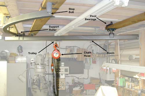
The answer came in a design that was a compromise between the bridge crane and jib crane ideas. It has the simplicity of the jib crane with the double-ended support and no floor space advantages of the bridge crane. The pivot point of the crane is done with a pair of flange type pillow blocks attached to the rafters. The support rail is made of 2" angle formed into a semicircle, the pivot point being at the center on that circle. The boom is a piece of barn door rail that is used for the sliding doors on barns and storage sheds. It is designed to support up to 400 pounds (although I'm not sure how they derived that). The trolley and rail were purchased at the same time from Triple-S for less than $30.
Constructing the crane.

The trickiest part of the crane has to be the fabricating of the semicircular rail. Originally I was considering sending it out to a place that could bend the 10 foot length of 2" angle, into an arc with a 60" radius. I suspect this would have been expensive and time consuming. One of our club members suggested making multiple cuts and re-welding it into the shape I needed. A lot of work, but it made sense. I knew my plasma cutter would cut a kerf about 0.050" wide when cutting 3/16 steel. If I were to take a 10 foot piece of angle and bend it into an arc with a 60" radius, it would cover about 120 degrees. This would allow the boom of the crane to cover the important areas of the shop. The difference between the length of the outside of the rail and the inside would be just over 4". (Since the two circles have a difference in radius of 2" (4" diameter) the circumference difference would be about 12.5 inches, and since the arc was 120 degrees, our piece would have to be shorter on the inside by a little over 4".) Dividing 4" by the 0.050" kerf, I found I would need at least 80 cuts. I decided to go ahead and error to the safe side and make a cut every inch. So I marked off, and made 119 cuts through one side of the angle.

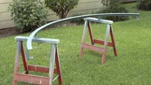
To build a form to bend the arc, I purchased a 4x8 piece of 3/4" particle board at Home Depot. I screwed the board down to a pair of sawhorses for stability. Since the radius was going to be 60", I screwed a piece of 2x4 to the bottom of the particle board centered and at a right angle to the long edge, and made sure it extended at least 14" from the edge. I then placed a screw, in the 2x4, that would become the center of the arc. Using a string and a pencil, I marked out the 60" radius arc on the particle board and cut it out with a saber saw. I then used a sander to radius the edge of the particle board to match the inside radius of the angle iron. If I were to do it again, I would cover the particle board with heavy aluminum foil where it touched the angle iron. This would help prevent gases from the particle board from getting in the weld.
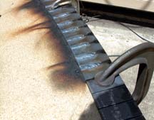
The angle was held down with C clamps and wrapped around the form. A few taps with a mallet assures that the angle was wrapped tightly. The welds were made about 1 inch long, I felt that it was unnecessary to weld the entire 2". Since the form was a little short, the piece was released, rotated slightly, and re-clamped. The rest of the welds were then done. The inside of the rail was pretty smooth, I cleaned up the bumps with an angle grinder.
Five tabs made of 2" angle were then welded to the structure using small pieces of 1" angle to strengthen the structure. I noticed the radius of the arc shrunk about 1.5" after welding. This is not a problem since the shrinkage was very consistent.
The next step is to layout the position of the semicircular rail in the shop. I placed the rail on the floor of the shop directly below where it would later be attached to the rafters. In this way I could easily visualize how much of the shop would be served by the crane, and where the pivot point would be. When I was satisfied with the position of the rail, I marked the position on the floor so that if I moved the rail, I could return it to the same location. Using a plumb bob, I was able to get a rough idea of where the bolts securing the rail would be. I then fastened 2x6's to the rafters for mounting the rail. The 2x6's were fastened to the bottom of the rafters with 4" screws, and safety brackets made from 1x1/8 flat steel. The brackets wrapped around the 2x6's and bolted through the sides of the 2x6's with 1/4-20 bolts. After mounting the 2x6's, a plumb-bob was used to pick-up the location of the rail mounting bolts. Marks were made on the 2x6's and 3/4" holes were drilled through. The large hole allowed for plenty of adjustment if necessary. The rail was then bolted to the 2x6's with 3/8" bolts and washers made from 2" square steel plate.
Now, find the precise center of the arc. One way to do this is to clamp a piece of 1" angle, or other straight material, across the ends of the rail. Carefully measure the distance from outside to outside of the arc along this straight edge. Divide the distance in half and make a mark on the straightedge. Then, measure the length along the outside of the arc, divide and mark the outside of the arc. If you then place a straight edge across the two marks, the center of the arc will be along that line. If you measure along the straight edge from the rail to a point equal to the radius, that should be the center. Mount another 2x6 so that the bearings for the pivot point will be supported. After the 2x6 is in place, you can put a nail in the 2x6 where the center should be. Using a piece of string looped around the nail, it should be possible to check the center by using the string to verify that the distance from the center to the ends and the middle of the rail are all equal. It will probably be necessary to move the nail and recheck a couple of times to get it right. Once found, drill the holes for the mounting of the two flange bearings. The shaft used on my pivot was 1", so I drilled the center hole to about 1-1/4" to allow for plenty of room.
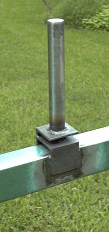
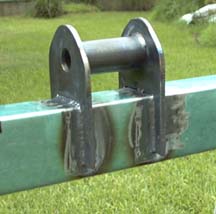
The boom must have the pivot and the roller assembly welded to it. First build the pivot assembly. In my design, I welded two pieces of 2" angle to the rail. Next I drilled the 1" hole for the pivot shaft through the angles. This was done on the mill to insure that the hole was at a right angle to the rail. Then, a piece of 1" shafting was welded into place. See the epilog for a better design that I came up with later. Temporarily install the pivot in the pivot bearings and swing the rail around to see that it swings in a level plane. The pivot bearings may have to be adjusted to make the rail swing properly. Mark the rail for the location for the roller assembly and the stop bracket located on the outside of the arc. Center punch the pivot shaft just above the top bearing. The shaft is then drilled through with a 3/16 drill for the #10 screw that is used to hold the shaft from falling through the pivot bearings.

The roller used in the roller assembly is a 6204 ball bearing I found in my scrapbox. The ball bearing will make the rail move smoothly, and support more weight than you would ever need. The bearing is mounted on a 1" shaft that was turned down to 20mm for mounting the bearing, the rest of the shaft was turned to .750 to fit the holes in the mounting plates. The shaft was parted off so that only about 1/8" of the 1" diameter remained. This is the flange that holds the bearing against the spacer. A cotter key holds the shaft in the mounting plates. See the photos and drawing for detail. A small piece of angle is used as a stop to prevent the boom from coming off the end of the rail. This device also prevents the rail from separating from the boom if the rail supports should break.
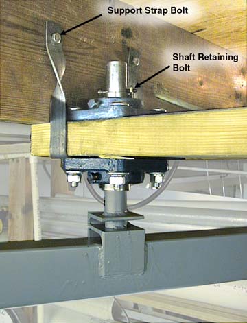
The trolley is made from the heavy duty trolley bought from Triple-S. A 3/8" bolt is dropped through the top of the trolley and connected to a forged eye hook used for the chain hoist. The eyebolt should be securely locked to the 3/8" bolt, but the assembly should be free to rotate in the trolley frame.
Storage of the Rotary Table
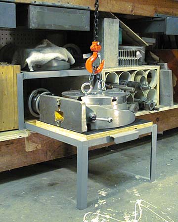
Since the whole idea of the project was to provide easier access and mounting of the rotary table on the mill, a convenient storage system for the rotary table was devised. Shown in the photo is the sliding storage shelf made for this purpose. It is made from 1" angle. The shelf holding the rotary table slides on the inside of the angle used for the frame. A stop prevents the shelf from being pulled out too far, and the legs on the front provide plenty of support for the heavy rotary table.
Epilog
As with any project, we learn things as we go. A better design for the pivot is shown in the drawing. In this case, a 1" pivot shaft is cross-drilled to accept a 1/2" diameter spacer. The spacer is made with a 1/4" through hole and is as long as the boom is wide. It is welded to the pivot shaft. Two plates are welded to the sides of the boom and a 1/4" hole is drilled through them. A 1/4" grade 5 or 8 bolt is used to secure the spacer between the two plates. The advantage of this system is that it allows the boom to self adjust to the height of the semicircular rail. This makes pivot bearing adjustment less critical. Also, it is much easier to remove the boom for maintenance.

