As promised in the February 1997 issue of the newsletter in "Desperate Men Do Desperate Things" here is the design of a stand with coolant for the 4x6 horizontal / vertical bandsaws.
This is a fun project to build because it gets away from the precision we normally work at and is simply a fabrication project. This is like the cabinet maker that takes a break and frames a house. Same material, different techniques.
The stand was designed to fit the saw I own. Some saws may be larger or smaller, so you may have to adjust the design to match your needs. The bottom of my tray is 24" by 12". This enables it to catch coolant dripping off the base casting without getting in the way of the motor (when the unit is set vertical), or the handle of the vise. Notice there is no detail on the mounting of the coolant tank. I used a tank and pump built by Little Giant. You may want to build your own tank or use a surplus pump. The tank and pump are held in a rack below in the bottom of the frame, it should be easy to configure a rack that suits your needs.
The first thing to build is the tray.
I built mine from 14 gage steel. To bend it, I cut a groove on the inside of the bend and used my vise and some angle iron to assist the bending process. On my tray, the sides are bent up at 60 degrees. This requires corner notches of 37 degrees. If you would like the sides to be at 45 degrees, then use an angle of 20 degrees.
Instead of bending the sides, it is possible to cut them out and weld the tray from five pieces. This is how I built one out of 1/8" steel about 4 years ago. It's a lot of welding, but it will work. If you bend up the sides, only the corners need to be welded.
The drain is the type used in wet-bar sinks. A hole was bored in the tray then a concave area for the drain was made using a shopbuilt hydraulic press. A little hammering could also be used to form the concave.
The next part to make is the Handle.
I made mine by clamping the 1/2" CRS rod in my milling vice. I made sure the same length was sticking out both sides of the vise, then I slipped a 3/4" pipe over each end and tugged. Before removing the handle from the vise, make sure the two ends are in the same plane and as parallel as you can get them. Two 8-32 holes are drilled and tapped, one in each end. After assembly, socket head screws will be used to prevent the handle from sliding out of the frame. In the photo, the handle is bent down slightly to help provide clearance for the vise handle. You can do this later if necessary.
The frame is built up from 11/2" angle iron.
The thickness of this material is 1/8". There are ten pieces that need to be cut. The piece marked "E" is actually made up from two pieces of material welded into a box. After welding this assembly and grinding the welds flat, drill the holes for the handle. Carefully measure the handle and drill the holes to fit. I used a 13mm drill, a 9/16 might do just as well. Piece "G" has two 1/2" holes for front feet. The feet were left over from an old project. Find some feet before you drill the holes so that things will fit properly.
The axle is made from 1/2" CRS.
Cut it to an appropriate length for your frame and wheels. I used 6" ball bearing wheels from Wholesale Tool. The wheels are held on by using 1/4" bolts threaded into ends of the axle. The 1/4" washer is just slightly larger than the shaft. This works real well for wheels with ball bearings. If your wheels have bushings, use the washer and cotter key approach, the bolts may unscrew.
First tack weld the frame together.
Pay attention to keeping things square. The axle is welded to the flat part of pieces H and I. That is why the 1/2" hole is so close to the edge. Use small welds to prevent warping the axle. Finish the rest of the welds on the frame, be sure to watch for warping.
The Frame for your coolant tank and pump should now be built.
I used 1" angle for mine. Two cross pieces from "H" to "I" and two length-wise pieces between them is all that is needed. I positioned the coolant tank in the front of the saw because it tends to be a little light in this area when using the saw in vertical mode.
Next weld the tray into place.
A few short welds at the corners and center of the sides should do the trick.
The saw is mounted on 2" square tabs of 3/16" CRS or similar steel.
Each tab has a 5/16-18 hole drilled and tapped for the saw. The tabs are bolted to the saw and then the saw is set into the pan. When you get the saw positioned where you want it, weld the tabs to the pan.
The nozzle for the coolant will vary from saw to saw because the structure of the saw guides vary.
My nozzle was made from a piece of 9/16" brass rod. It is
drilled 5/16" 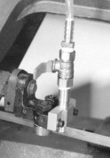 from
the top end to just short of the bottom end. The lower end was
turned to .500" diameter, and the top end was turned and
threaded 1/4" NPT. The lower end was slit for a distance of
1/2" using a 1/16" slitting saw. This does a good job
of keeping the coolant on the saw blade and off the floor. A ball
valve is used to control coolant flow. Do not use a gate valve,
although they adjust nicely, they are a pain to turn on and off
quickly. The holder for the nozzle was made of aluminum and
fastens to the front of the blade guides using two 10-32 socket
head screws in elongated holes. The .500" hole in the holder
was bored .240" back from the edge. This causes the holder
to bend and clamp the nozzle when the two screws are tightened.
The nozzle can be adjusted for height, side clearance and
rotation. All these are locked into place when the screws are
tightened.
from
the top end to just short of the bottom end. The lower end was
turned to .500" diameter, and the top end was turned and
threaded 1/4" NPT. The lower end was slit for a distance of
1/2" using a 1/16" slitting saw. This does a good job
of keeping the coolant on the saw blade and off the floor. A ball
valve is used to control coolant flow. Do not use a gate valve,
although they adjust nicely, they are a pain to turn on and off
quickly. The holder for the nozzle was made of aluminum and
fastens to the front of the blade guides using two 10-32 socket
head screws in elongated holes. The .500" hole in the holder
was bored .240" back from the edge. This causes the holder
to bend and clamp the nozzle when the two screws are tightened.
The nozzle can be adjusted for height, side clearance and
rotation. All these are locked into place when the screws are
tightened.
The line from the coolant pump is 3/8" vinyl tubing.
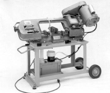
The pump came with 1/2" tubing, but this takes too long to fill and empty between cuts. The pump motor is permanently wired across the saw's motor. That is, whenever the saw is sawing, the pump is pumping. When used in the vertical position, turn off the coolant at the ball valve. In this way the wiring is kept simple. Notice in the photo of the finished stand, the small jar under the tailpiece of the drain. Small metal chips will collect in the jar, only clean coolant returns to the tank.
Good-luck with your new saw stand.
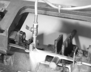
The saw in action, cutting a 1" bar of 1018 steel.
Download Drawings of Sawstand in PDF Format (30K)
