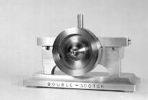
The Double Scotch
In browsing through my copy of Elmer's Engines, by Elmer Verburg, I ran
across a steam engine he named "Scotty". This engine used a scotch
yoke to translate the reciprocating motion, of the piston to the rotary motion
of the output shaft. The engine had a one single acting horizontal cylinder. A
sliding support was necessary at the opposite end of the connecting rod from
the piston. Another feature was that the crank-shaft was used as a rotary
valve. A neat little engine, but we need MORE POWER. Instead of using a support
for the connecting rod, this design uses another piston and cylinder. In place
of the rotary valve, my design uses a spool valve driven by another scotch
yoke. Two scotch yokes, one converting reciprocating to rotary, the second
convert rotary to reciprocating, hence the name "Double Scotch".
The drawings are in Adobe Acrobat 3.0 format. This is to provide the builder
with high quality drawings with minimal download time. Acrobat also preserves
the vector base information so that the drawings can be enlarged as much as
desired without losing resolution. If you do not have Acrobat 3.0, download it
for free right here.
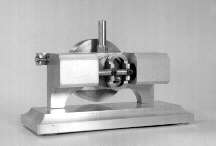
The engine is very smooth and will run on air as low as 1 PSI. Operation of
the engine is simple. Air or steam is introduced through the INLET at the top
center of the engine. The 3/16" passage-way through the FRAME ducts the
steam to valves at each end of the engine. The disk of a valve either directs
steam into the cylinder from the passage way, or releases steam from the
cylinder into the atmosphere, at each end of the engine. Timing for the valve
is generated by an eccentric on the backside of the flywheel.
Most parts of the "Double Scotch" are made from 6061 Aluminum. The
ball bearing is quite small, 3/8" diameter with a 1/8" bore. A
bushing made from bronze or brass would also work well. Notes for the
construction of the "Double Scotch" are given below:
Construction Notes
- MAIN BEARING - Turn from brass or bronze. Bore or ream to fit
available 1/4" drill rod.
- CYLINDERS - Two cylinders are made as opposites. The cylinder for
the left side (facing the cylinders) is shown in the drawing. The cylinders are
made from 6061 aluminum. The bore can be drilled then finished with an end
cutting endmill to a depth of 1.062". The diameter is not real critical
because the piston can be fitted later. The hole must be smooth, round, and
have straight sides. The small hole used to allow steam into the top of the
cylinder is first drill with a 3/32" drill bit to a depth about
0.030" full diameter. The 1/16" hole can now be drilled at an angle
suitable to come through into the cylinder, just about center. This is not too
critical. The two 4-40 threaded holes are drilled and tapped to a depth of
3/8".
- PISTONS - The pistons are turned from brass. They should be made
after the CYLINDERS so that they may be made to fit. About 0.001 to 0.002
undersize is good. Cut a few shallow oil grooves in the outside of the piston
to aid lubrication and sealing.
- CRANKSHAFT - The crank is made in two pieces then silver soldered
together. The disk is made from mild steel, the shaft from drill rod. Make the
disk a little thicker than final size to allow for facing after the silver
soldering.
- FLYWHEEL - The flywheel is made from 2" diameter mild steel.
Because part of the flywheel is the eccentric to operate the valves, it is not
a good idea to use aluminum. Face the disk and layout the center of the
flywheel and the eccentric. Place the blank in a 4-jaw and adjust to make the
eccentric center runs true as well as the face. Cut the eccentric 0.500"
diameter and .094 wide. Set the blank so the flywheel center runs true as well
as the face. Cut the 0.031 step then drill and ream the 1/4" hole. Reverse
the blank and make the cuts on the front side of the flywheel. These cuts are
mainly cosmetic. Drill and tap the 6-32 hole for the setscrew.
- FRAME - The frame is made from 3/8 aluminum. The steam passage
should be carefully drilled from each end with an under size drill bit, then
reamed to 3/16 all the way through. The hole for the inlet is drilled and
tapped to a convenient size. I used 1/4-32. A fine thread is necessary, 10-32
would work OK. Drill the other holes as indicated, be careful to locate them
accurately.
- MAIN SCOTCH YOKE - This is a neat little part made from aluminum.
The profile on the outside is not critical, but the inside dimensions and the
shaft mounting seat are critical. The two 2-56 holes are drilled and tapped
through.
- VALVE YOKE - Start out with a piece of aluminum 3/8" x 4"
x 1 1/32" and cut away 90% of it. One tip: cut the part to thickness
first, then cut the oval cutout, then cut the profile on the outside.
- PISTON ROD - Turn from 3/16 mild steel. Spot face the two holes for
#2 socket head screws.
- SPOOL VALVE ASSEMBLY - This could be made from the solid, but it is
much easier to make it up from a piece of 1/16" brazing rod and some small
disks. Make the disks from brass 3/16" diameter, 3/32" thick, with a
1/16" hole in the center. Measure your 1/16 rod, mine was a bit smaller,
so I drilled a little smaller hole in the disks. Use a piece of 1/16"
brazing rod a little longer than what is needed. Soft solder one of the inside
disks into place. Mark the shaft 3.125" from the first disk and solder the
second disk. Use the VALVE YOKE to hold the 1/16" rod while the two end
disks are soldered in place. The will help assure a snug fit from the yoke to
the valves.
- CRANK SCREW - Make this small screw from drill rod or mild steel.
Cut the 0.125" shoulder so that it will be a light press fit into the ball
bearing. If you do not have a bearing, make one from brass on bronze. The
dimensions are: 0.375" diameter, 0.156" thick, bore 0.125"+ for
rolling fit.
Assembly
- Assembly and fit-up are pretty simple. The drawings of the completed engine
should be helpful.
- To make sure the cylinders match-up try the following trick. Take a short
length of 1/2" drill rod, say 3"long. Slide the two cylinders over
the drill rod, and lap the sides that mount against the frame on a piece of 400
grit SC paper with a little oil for lubrication. This will help assure that the
pistons will not bind when the assembly is put together. Also, leaving the
pistons slightly loose on the piston rod can help if things are not quite
right. Apply Locktight to the threads on the end of the piston rod before
assembly.
- If the ball bearing fits loose on the Crank Screw, or you are using a
bronze bushing, make a small washer 1/4" in diameter and 1/8" bore
for use between the bearing and the crankshaft disk.
- Use 1/4" 2-56 socket head screws to secure the Piston Rod to the Main
Yoke.
- Fasten the Cylinders to the Frame using four 5/8" 4-40 flat head
screws.
- To prevent the Valve Yoke from catching on the end of the Main bearing,
make a washer from 0.005" brass shim stock. The washer should have an O.D.
of 1" and an I.D. of 1/4". Place the washer on top of the main
bearing before the Valve Yoke and Flywheel are installed. The Flywheel requires
a 3/16" 6-32 set screw.
- To set the valve timing, turn the crank until both pistons are in the
center of their travel. Then while holding the Crankshaft still, turn the
Flywheel until the Spool Valve is at it's furthest travel, then lock-down the
setscrew on the Flywheel.
- There are two tapped holes in the bottom of the Frame. These are used to
mount the Double Scotch to a suitable base. I used a 2" x 5" x
3/8" piece of aluminum plate as the base. A 5/8" ball end mill was
used to provide the decorative edge around the top of the base. Two socket head
cap screws, 8-32 x 1/2", were used to hold the engine to the base.
- Break-in the engine using compressed air. Only five to ten PSI should be
required. Use plenty of oil during break-in.
Download drawings
Right click on file name and
select "Save Target As.."
Acrobat Format dscotch.pdf
(111K)
.gif format (2 files) dscotch_assembly.gif
(15K) dscotch_drawing.gif
(91K)

2/4/97