MAKING WEDGE TYPE TOOLHOLDERS
By Keith Mitchell
Recently I purchased a wedge type quick-change toolpost for my lathe.
The toolpost is of course only the start. Now you need multiple toolholders
to get the benefit of a quick-change toolpost. Depending on which one you
select these toolholders cost from $25 to $50 in the import grade. Knowing
that I would not be satisfied with less than a full complement and being
unwilling to spend the money on this many toolholders, I set out to make
my own. Afterall, on initial inspection, it amounted to only a block with
a dovetail slot, a straight slot and a few drilled and tapped holes. I
purchased a 60-degree dovetail cutter and proceeded to make some chips.
I had purchased two toolholders so I measured the dovetail slot in each
and attempted to replicate it in the new part. My first attempt produced
an unusable part when I machined the dovetail too large. Both the width
and the depth of the slot determine the fit of a dovetail. I found
it to be difficult and time consuming to accurately measure the dovetails
while they are being machined. The most accurate procedure to measure width
of a dovetail involves placing two rods or balls of known diameter in the
dovetail slots and measuring between them. It quickly became apparent that
a sizing gage would be very helpful in machining the dovetail.
I set out to make a male tapered dovetail gage. 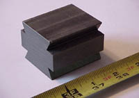 The gage I made had two sides. The smaller side will pass completely through
the completed dovetail and is used to warn when you are approaching final
dimension. The large side will wedge part way through a completed toolholder
dovetail and is used for the final sizing. The 0.020" taper over the length
of the gage was achieved by machining one side of the dovetail to full
depth then installing shim stock at opposite corners of the gage block
in the mill vise to cause the taper. 1-1/2 X 2" aluminum stock was selected
for the gage. CRS would be better since it is not as susceptible to dents
and dings during storage and use. I had my gage block hard anodized to
make it less susceptible to damage. For this type of work I find it easier
to mount the work in the vise and find the center of the piece. Then work
from the center out. The straight side was machined to full depth first.
Then the shims are installed and the taper machined. I used a purchased
toolholder to check the gage as I machined the tapered side. Of key importance
is the fact that the outside corners on the dovetail are not sharp corners,
they are radiused or broken. As the gage is machined you must make sure
the corner breaks are maintained. Use a file or periodically replace the
dovetail cutter with an end mill to break the corners. If the corners are
not adequately broken, the gage will not fit until it is seriously undersized.
Go extremely slowly as you approach final size. I made the last few passes
with a 0.002 cut. Ideally the final sizing gage will fit the sample dovetail
when it is inserted about halfway or a little more.
The gage I made had two sides. The smaller side will pass completely through
the completed dovetail and is used to warn when you are approaching final
dimension. The large side will wedge part way through a completed toolholder
dovetail and is used for the final sizing. The 0.020" taper over the length
of the gage was achieved by machining one side of the dovetail to full
depth then installing shim stock at opposite corners of the gage block
in the mill vise to cause the taper. 1-1/2 X 2" aluminum stock was selected
for the gage. CRS would be better since it is not as susceptible to dents
and dings during storage and use. I had my gage block hard anodized to
make it less susceptible to damage. For this type of work I find it easier
to mount the work in the vise and find the center of the piece. Then work
from the center out. The straight side was machined to full depth first.
Then the shims are installed and the taper machined. I used a purchased
toolholder to check the gage as I machined the tapered side. Of key importance
is the fact that the outside corners on the dovetail are not sharp corners,
they are radiused or broken. As the gage is machined you must make sure
the corner breaks are maintained. Use a file or periodically replace the
dovetail cutter with an end mill to break the corners. If the corners are
not adequately broken, the gage will not fit until it is seriously undersized.
Go extremely slowly as you approach final size. I made the last few passes
with a 0.002 cut. Ideally the final sizing gage will fit the sample dovetail
when it is inserted about halfway or a little more.
Once the gage is completed, you are ready to start machining the toolholder
blocks. The attached drawings are for a BXA or a 200 series size toolholder
in the import brands. Other sizes will require different dimensions. I
used 1-1/2" X 3" CRS for the tool holder blocks in the photos. I have also
used a 2" X 6" X 12" slab of 4130 for toolholders. Since making the dovetail
cut is a time consuming operation, I like to start with enough material
to make about four or five toolholders, usually a 6 to 7-1/2" length. When
you size the material make sure you allow for the saw cuts and cleanup
machining which will be required later. 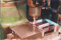 My
rule of thumb on saw cuts is to allow at least 0.050" additional material
to clean up each saw cut if your saw is pretty well setup to cut straight.
That's 0.100 for saw cuts on both sides. The dovetail slot is cut in the
long axis. Then cut the block on the bandsaw into the separate toolholders
for finishing. I machine the center slot with a straight 3/4" end mill
first. The dovetail cutter I use is a1-3/8" diameter HSS, so the 1.400"
slot width will clear the dovetail cutter and breaks the inside corners
sufficiently to clear the gage. The initial cuts with the dovetail cutter
can be a little aggressive since not much material is being removed. As
the dovetail develops, the depth of each pass should be reduced. As final
dimension is approached, use the gage often. The last cuts are made with
a feed of about 0.001 - 0.002" per pass. I can tell you from experience,
it's a sick feeling to make the final cut and find that the gage block
drops right through. I've sucessfully salvaged some blocks cut oversize
by tig welding one side of the dovetail, however, it's easier to get it
right the first time. MAKE SURE THE CORNERS ARE ADEQUATELY BROKEN! Otherwise
the gage block may not pass due to
My
rule of thumb on saw cuts is to allow at least 0.050" additional material
to clean up each saw cut if your saw is pretty well setup to cut straight.
That's 0.100 for saw cuts on both sides. The dovetail slot is cut in the
long axis. Then cut the block on the bandsaw into the separate toolholders
for finishing. I machine the center slot with a straight 3/4" end mill
first. The dovetail cutter I use is a1-3/8" diameter HSS, so the 1.400"
slot width will clear the dovetail cutter and breaks the inside corners
sufficiently to clear the gage. The initial cuts with the dovetail cutter
can be a little aggressive since not much material is being removed. As
the dovetail develops, the depth of each pass should be reduced. As final
dimension is approached, use the gage often. The last cuts are made with
a feed of about 0.001 - 0.002" per pass. I can tell you from experience,
it's a sick feeling to make the final cut and find that the gage block
drops right through. I've sucessfully salvaged some blocks cut oversize
by tig welding one side of the dovetail, however, it's easier to get it
right the first time. MAKE SURE THE CORNERS ARE ADEQUATELY BROKEN! Otherwise
the gage block may not pass due to 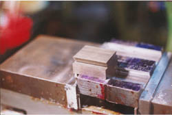 interference
from the sharp edges. If this happens you will get a false indication from
the gage. Also make sure the chips are well cleared so they don't interfere
with a good reading from the gage. I keep a 1" chip brush handy to clear
the chips.
interference
from the sharp edges. If this happens you will get a false indication from
the gage. Also make sure the chips are well cleared so they don't interfere
with a good reading from the gage. I keep a 1" chip brush handy to clear
the chips.
I like for my toolholders to close within 1/4 turn. This ensures the
toolpost handle is not in your way when it is closed. To achieve this I
usually machine the toolholders slightly undersize and then do the final
fitup by hand using a file and emery cloth after they are cut into individual
holders.
Once the main block is machined, I bandsaw the individual toolholders
from the block. Do a cleanup operation on the saw cut ends to square up
the block. I like to use a flycutter for this operation since it will cover
a large area in minimal time. Also with a flycutter two blocks can
be machined at the same time by putting them in the milling vise back to
back. A shot on the belt sander with 120 or 180 grit will remove the tool
marks.
To make toolholders for 1/2" tooling place the block in the milling
vise to cut the slot for the tool. I use a 5/8" wide X 1/2" deep slot for
most of my lathe tool blocks. It works for a number of tools. If you wish
to use 1/4" or 5/16" HSS toolbits they can be used by making a carrier
from 1/2" square stock with a suitable slot milled.
Once the tool slot is cut turn the block in the milling vise to drill
the holes for the height adjustment screw and the tool set screws. I used
a 3/8-24 thread for the height adjustment screw. The fine thread makes
it easier to get the height set accurately. In addition, the knurled height
adjustment nut is not very thick and needs the fine thread to get adequate
thread engagement. The tool holding setscrews are also 3/8-24 to keep it
simple to drill holes and tap.
The knurled height adjustment nut is made from 1" diameter 12L14 rod.
When turning, I like to have plenty of material to grip in the chuck so
I start with a piece about one foot long. Like the toolholder blocks I
like to make several of these at a time. Put the stock in a three-jaw chuck
in the lathe. I usually cleanup the surface with some Scotchbrite either
by hand or with a disc in a 1/4" angle head die grinder. Face the end.
Center drill and tap drill a hole for the 3/8-24 thread in the center of
the rod in the lathe. Chamfer the outside end about 0.050".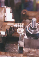 Using a cutoff tool layout the number of knurled nuts you plan to make.
I usually set up a dial indicator on a magnetic base to space the nuts
for cutoff. Bring the cutoff tool up even with the outboard end of the
stock. Step off the width of the nut plus the width of the tool. At each
location make a cut about 0.100" deep. Return to each location and cut
a chamfer on both sides of the cutoff tool slot to match the end chamfer.
Set up the knurling tool. I used medium diamond wheels in the knurling
tool. Put the lathe in backgear, apply cutting oil and knurl all of the
nuts in one operation. If you try to knurl first then cut-off, I find the
edges of the nuts are upset slightly and are not as nice to use.
Using a cutoff tool layout the number of knurled nuts you plan to make.
I usually set up a dial indicator on a magnetic base to space the nuts
for cutoff. Bring the cutoff tool up even with the outboard end of the
stock. Step off the width of the nut plus the width of the tool. At each
location make a cut about 0.100" deep. Return to each location and cut
a chamfer on both sides of the cutoff tool slot to match the end chamfer.
Set up the knurling tool. I used medium diamond wheels in the knurling
tool. Put the lathe in backgear, apply cutting oil and knurl all of the
nuts in one operation. If you try to knurl first then cut-off, I find the
edges of the nuts are upset slightly and are not as nice to use.
After knurling set up the cutoff tool again. Re-enter the cutoff tool
slots and cutoff each nut. If you end up with a burr on the free side,
install a short piece of 3/8-24 threaded rod in the stock remaining in
the chuck. Install the nut on the rod so the threaded rod is slightly underflush.
A few light facing cuts will cleanup the burr.
Assembly is pretty simple. The height adjustment screw can be a long
setscrew; however, a piece of allthread works as well. The height adjustment
screw is Loctited into the toolholder block.
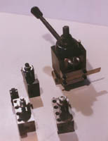
The drawings show a cutoff tool, a toolholder for 1/2" shank tools and
a boring bar holder. All of the boring bar toolholders are made for 3/4"
boring bars. For smaller boring bars I have a split sleeve to reduce the
diameter. The extra bushing with the face key is used with boring bars
to index them in the holder. The diameter of the center hole is adjusted
to fit the boring bar. A friend has a toolholder which he really likes
that takes 5C collets.
I'm considering having a gunsmith friend blue my toolholders for the
final finish if I can catch him when his tank is hot. Now you can have
a separate toolholder for every tool and get maximum benefit from your
quickchange toolpost. No more swapping tools between toolholders.
I have seen another technique for making dovetails I may consider trying.
This technique uses a built up method. Two rails are machined with the
dovetail angle. These are silver soldered to a block at the correct spacing
to make the dovetail. I have not tried this so I can not tell you if it
would work. If I give it a try I'll let you know. Many thanks to George
Carlson for processing the drawing that accompanies this where it loads
quickly and is legible.
Questions:Keith Mitchell
8/22/99
Download Adobe Acrobat Version of drawing
(22K)
