Volume 7, No 8 - August, 2002
|
|
Volume 7, No 8 - August, 2002 |
|
|
|
|
|
| President - |
Vice President - |
||
| Treasurer - |
Secretary - |
||
| Webmaster - |
Editors - |
||
|
|
|
SIG Coordinator - |
Membership Information
Membership is open to all those interested in machining metal and tinkering with machines. The purpose of the club is to provide a forum for the exchanging of ideas and information. This includes, to a large degree, education in the art of machine tools and practices. There is a severe shortage of written information that a beginning hobbyist can understand and use. This makes an organization such as this even more important.
Zube Park Metal Pour
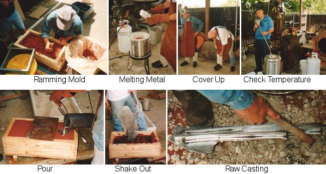
On July 6th members of the casting SIG held a metal pour at Zube Park, Houston, TX. They explored ways to cast a frog, part of a railroad switch or turnout. The Houston Area Live Steamers at Zube Park need this component for their track expansion. Three casting methods were tried; open mold with a filler on the bottom of the pattern, open mold without the filler, and two part mold with a sprue at one end and a riser at the other. At the next regular club meeting, the results will be compared and the best approach announced.
Business Meeting
Minutes are sent via email or regular mail to club members.
Regular Meeting
Collier Library. Houston, TX. July 13, 2002. 1:00 pm. There were 38 attendees including visitors from Austin TX; S. Ripple and J. Scott.
The next swap meet was discussed. We prefer being hosted by a local supplier having surplus to dispose of in conjunction with the usual member junk
Club members are available to advise surviving spouses on the value of shop items to be sold. Fourteen volunteers offered to be first on the scene. Contact club officers for arrangements.
Dennis Cranston and Art Volz volunteered to represent the CNC and casting groups.
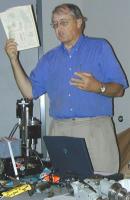
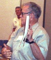
Presentation
|
Dennis |
Bill |
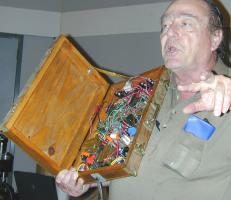
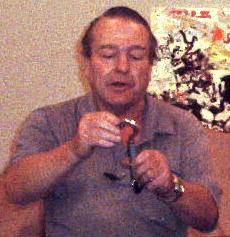
The focus was to show members first attempts at computerizing mechanical equipment using CNC (Computer Numerical Control). Dennis Cranston showed a Sherline mill that he had computerized around 1990. CNC information at that time was sparse. The 5 volt stepper motors were powered by a supply from an original IBM PC. The driver was designed around MJE102 transistors controlling the stepper motor windings, The transistors were in turn controlled by a parallel port on a PC. The controller program was a recent version of the program originally written in 1990. Examples of the work demonstrated that getting results from homebrew CNC was not that complicated. (ed. Maybe to some people!) Bill Swann showed a preliminary package for winding coils. Using an 8051 micro-controller, a user is able to input the desired parameters on a keypad in response to questions shown on an LCD. Once the parameters are entered, the micro-controller drives the steppers to wind a coil on a bobbin. Art Voltz showed a stepping motor control circuit built in a wooden box. This circuit was designed to be controlled from ports on the TI990 micro-computer produced in the mid 80's. |
|
Art Volz |
||
Show and Tell
|
|
|
 Doug Chartier showed his newly acquired Gorton tool grinder parts. A super buy on eBay. He even got a great shipping rate. |
|
Casting SIG
The presentation for August will feature the Casting SIG. Results from the Zube park pour will be reviewed. Alloying and use of low temperature castable metals will be discussed
From out of the Past
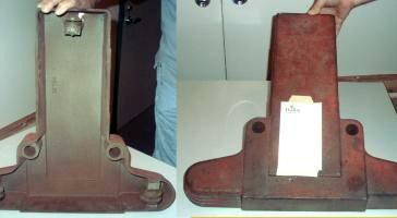 The item pictured in the July newsletter was the base stand for
a head light alignment machine that used to be so common in filling station bays.
The item pictured in the July newsletter was the base stand for
a head light alignment machine that used to be so common in filling station bays.
Fastener Puzzler
 Last
month's fastener puzzler generated just one completely correct response.
Here is Jan Rowland's answer.
Last
month's fastener puzzler generated just one completely correct response.
Here is Jan Rowland's answer.
In Fig. 2,
since F (1800 lb.) is less than the spring-tension (2000 lb.), nothing moves.
The spring-force on the nut, and hence the bolt, is 2000 lb, less than the 3000 lb.
yield-strength of the bolt.
Featured Articles
|
|
|
|
|
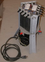
Anti-Vibration Machine Mount by Dick Kostelnicek |
|
After installing a 7.5 HP rotary phase converter on the wood deck just outside my shop, I found that for loads in excess of 5 HP the converter vibration, amplified by the sounding board effect of the deck, was objectionable. I quickly drove out to a nearby freeway to look for a recap tread flung off of a large truck tire. Recap treads make rather nice damping pads when placed under vibrating machines. They don't have steel cords imbedded in the rubber, are about 5/8 in thick, and therefore, can be band sawed into slabs of any shape. However, what I came upon was a very long serpentine fan belt lying on the road's shoulder. I hope the guy who dropped it got home OK. The accompanying photos chronicle my adaptation of this rubber belt material into anti-vibration motor mounts.
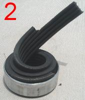
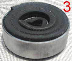
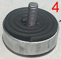
Fig. 1. shows the parts for each mount. The ring retainer was sawn from 2 in. thin-wall EMT (electrical metallic tubing). The washer and four-holed disk were made from 1/8 in. aluminum plate. The piece of serpentine belt has a notched end that accommodates the head of a carriage bolt. Fig. 2. shows the belt material being coiled inside the retaining ring. The mount's bottom, with a cavity for the bolt head, is shown in Fig. 3. The top of the mount, with the bolt inserted, is shown in Fig. 4. If you are going to make these mounts, consider drilling the hole in the top washer off-center by half the belt's thickness. Then rotate the washer about the bolt that itself is forced off-center because of the belt's starting edge against the retaining ring. This will create a good-looking concentric fit between the washer and the retainer.
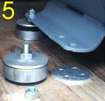
In Fig. 5., the anti-vibration mounts are installed under the rotary converter's motor base flange. The flange is cinched between both nuts on each of the mount bolts. Aluminum disks, having four countersunk holes, are screwed to the wood decking. These disks were made to slip easily inside the retaining ring. Finally, as can be seen for the mount at the rear of the motor's flange, the retaining ring is pulled down over the decking disk in order to prevent the converter from walking around.
The belt material contains only non-metallic fibers so I was able to band saw it at the same speed as aluminum. A serpentine belt has grooves cut in one face, which appears to enhance the vertical elasticity of the mounts. Whether the belt's grooves should be facing in or out, I'll leave that to your discretion. I have my thoughts on the subject. But, some things just must remain proprietary,
|
|
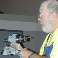
Maintaining by Joe Scott - HMSC Member |
|
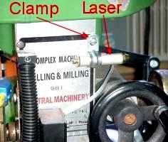
If you ever used a mill-drill, you probably have been frustrated in keeping the spindle positioned when you move the head up and down. Most mill-drill heads are not adequately keyed, if at all, to the supporting column. Hence, you loose the tool position relative to the table when more or less clearance is required over the work.
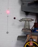
Well, the solution is really quite simple. I used of a $5 laser pointer and a string with a plumb-bob. Mount the laser pointer horizontally to the mill's head. I used a metal cable clamp. Hang the string and plumb-bob from your ceiling as far away from the mill as possible. Make sure the machine is level and that the column is absolutely vertical. Using a dark string close to a light colored wall makes it all the easier to see the laser spot. As you move the mill's head up an down, maintain the spot on the string.
|
|
|
by Dick Kostelnicek |
|
|
|
|||
|
The next meeting will be held on Saturday August 10, 2002 at the Collier Library 6200 Pinemont, Houston, TX at 1:00 p.m. Bring along a work in progress to show. Visit Our Web Site |
 |
Right click below then select [Save
Target As...]
From Netscape select [Save Link As..]
Microsoft
Word version of this newsletter 331 KB


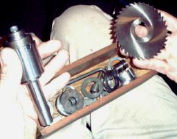 Joe Williams showed a Peterson Flush Stub Arbor
used to hold circular cutters. It was manufactured in the early
40's and works by internal expansion instead of side clamping.
Joe Williams showed a Peterson Flush Stub Arbor
used to hold circular cutters. It was manufactured in the early
40's and works by internal expansion instead of side clamping.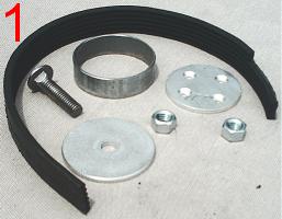
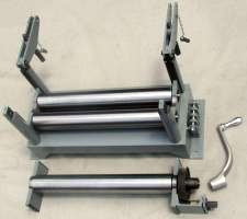
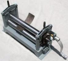
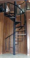 Here's my version of a
18 in. slip roll. It was originally made to roll flats and square tubing in
order to construct railings for a spiral stairway. The base is a weldment. It uses 2
in. schedule 80 pipe as rollers supported by ball bearings. The top
roll slides up and down to accommodate various work thickness and
bend radii. It is driven by a hand crank through a 4-to-1 gear
reduction. Originally, I made the rollers from schedule 40 pipe and ended up
necking down the top roller while bending 1-1/2 in. square tubing. The top
roller encounters twice as much force as either of the bottom ones, and
therefore, has larger support bearings. The bend radius is progressively
increased by tightening the two top vertical bolts about 1/4 turn for
each pass of the work being rolled.
Here's my version of a
18 in. slip roll. It was originally made to roll flats and square tubing in
order to construct railings for a spiral stairway. The base is a weldment. It uses 2
in. schedule 80 pipe as rollers supported by ball bearings. The top
roll slides up and down to accommodate various work thickness and
bend radii. It is driven by a hand crank through a 4-to-1 gear
reduction. Originally, I made the rollers from schedule 40 pipe and ended up
necking down the top roller while bending 1-1/2 in. square tubing. The top
roller encounters twice as much force as either of the bottom ones, and
therefore, has larger support bearings. The bend radius is progressively
increased by tightening the two top vertical bolts about 1/4 turn for
each pass of the work being rolled.