Volume 8, No 1 - January, 2003
|
|
Volume 8, No 1 - January, 2003 |
|
|
|
|
|
| President - |
Vice President - |
||
| Treasurer - |
Secretary - |
||
| Webmaster - |
Editors - |
||
| Founder - |
SIG Coordinator - |
Statement of Purpose
Membership is open to all those interested in machining metal and tinkering with machines. The club provides a forum for the exchanging of ideas and information. This includes, to a large degree, education in the art of machine tools and practices. Our web site endeavors to bring into the public domain written information that the hobbyist can understand and use. This makes an organization such as this even more important.Business Meeting
Minutes are sent via email or regular mail to club members only.
Regular Meeting
Collier Library, 6200 Pinemont, Houston, Texas. December 14, 2002. 2:00 pm. There were 3 visitors: Leo Reed, Skip Evans, and Mike Buelu.
The January meeting will start at the regular time, 1:00 pm.
Dennis Cranston, Librarian, brought videos to the meeting for check-out. Next month, books. Remember to bring back all checked-out library items to the January meeting!
Presentation
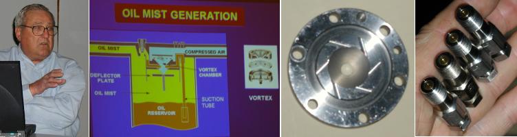
Fred Paben, Training Lubrication Specialist, at Lubrication Systems Company discussed the LubriMist� centralized oil mist system. This lubrication technique uses low pressure, 7 psi, compressed air to produce a lean mixture of atomized, 3 micron, oil that is distributed through tubing to bearing housings. Both roller and ball bearings can be retrofitted with this system. The spent oil can be vented or captured, recirculated, cleaned, and reused in a closed loop system.
Show and Tell
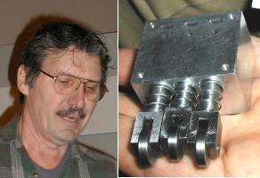
John Hoff showed a homemade cam-actuated multi-port air valve employing sliding spindles with O-rings for a manufacturing machine that he is building. |
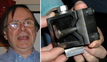
Dick Kostelnicek showed a V-notch, auto centering, boring bar holder that replaces the toolpost on his lathe's compound slide. |
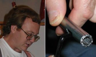
Gordon Lawson showed a homemade hole saw fabricated from tubing with hand filed teeth. |
Jeff Robinson showed a cylinder assembly for a 7-1/2 gauge steam engine he is making. |
R. J. Rouse showed some quick and dirty production tools. He also discussed bearing failures and showed some odd shaped recovered roller bearing balls. |
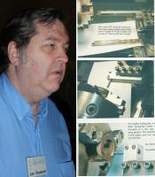
Jan Rowland presented a poster showing various techniques and fixtures that he uses for holding boring bars. |
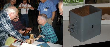 The Casting
SIG looked over a flask that Ed Gladekowski made from a piece of
large square steel tubing They discussed a better way to make
the rubber-plaster molds brought in by Dennis Cranston. Joe Williams suggested
making a plaster backing to the rubber mold which could be smoothed parallel
with the face of the master pattern.
The Casting
SIG looked over a flask that Ed Gladekowski made from a piece of
large square steel tubing They discussed a better way to make
the rubber-plaster molds brought in by Dennis Cranston. Joe Williams suggested
making a plaster backing to the rubber mold which could be smoothed parallel
with the face of the master pattern.
An ad-hoc committee
discussed building a molding bench at the club foundry that is located at Zube Park. The
bench should be at least eight foot in length, allow two people to work at the same time,
and have access from both sides.
Computer Numerical Control SIG
No activity this Month.
The next meeting will cover Homebrew CNC. What's going on in your shop.
Featured Articles
Grinding Your Own Carbide-Tipped Cutting-Tools
by Jan Rowland - HMSC Member
Somehow, I managed to learn early-on in this home-machining avocation that tooling tipped with tungsten-carbide, or sometimes even better, �solid carbide� (shank and all) is often vastly better for cutting several kinds of material, even some �softer� than metals. Even professional woodworking tools are usually carbide-tipped! I was once in the pipe-organbuilding industry, essentially one in which large �machines� are built mostly of wood, but the work is �machinist precision�, not �carpentry�. In that, I began glibly using carbide-tipped saw blades, router-bits, shaper-cutters, kinda assuming �everybody did that� Years into that, I ran into a colleague who scoffed, saying that �Carbide doesn�t cut nearly as nicely as high-speed steel!� To make a long story short, I had been lucky in using a �saw shop� for sharpening such tooling that used diamond grit wheels, and the result was razor-sharp, yes, even better than that myopic colleague�s luck. Turns out his �saw shop� was owned/operated by a senior gentleman who still used only �green wheels� for grinding carbide, and those with any experience with such realize that it may �grind away� some carbide, but it �rounds off� edges that should instead be razor-sharp.
 So,
once I found myself on my own, in need
of the ability to grind carbide tooling, more to custom-make than just
sharpen, I had to find out how to do diamond-wheel work acceptably economically,
without having to purchase a $10,000 machine for that!
So,
once I found myself on my own, in need
of the ability to grind carbide tooling, more to custom-make than just
sharpen, I had to find out how to do diamond-wheel work acceptably economically,
without having to purchase a $10,000 machine for that!
�Brazed-on� lathe-tooling generally comes rather dull; with an edge with a visible radius! Perhaps that may be OK for �rough-cutting� steel, but hardly good for aluminum, or precision in brass, etc. And, though very, very hard, the carbide does wear, and it sometimes chips when the user is not obeying all the rules conservatively. Thus, we have the perhaps-most-common need to do diamond-wheel work. (Don�t tell anyone, but even grinding a throw-away insert is often economically preferable, and/or one might need a �custom angle� or tip-shape, etc.)
The first time one sees a �diamond wheel�, only to discover it is only 1/8� thick, is 95% aluminum, with only 1/8� deep �brown stuff� called �diamond compound� around the circumference, he might be a bit shocked to find it is priced around $100 a copy! But if such a wheel is treated with the respect its price suggests, it should last through hundreds of grinding-operations. Part of this respect, if the grinding be done dry, as discussed here, would be to take no more than 0.001� off, per pass, making those passes sufficiently slow that the only swarf coming out of the grind is carbide-dust, not diamond-compound dust.
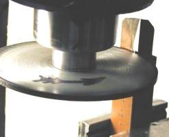
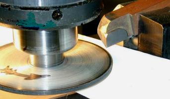 The
left photo shows a �� carbide-tipped brazed lathe-tool being sharpened, held in a vise
on a vertical mill, the diamond-wheel mounted to a (home-brew!) arbor in a
collet in the mill�s R8 quill. For
manual-lathe tooling, �eyeballing� of set-up angles is generally sufficient, but
you can see here I began taking a few mils more off the trailing edge of the
tip. The �shiny grind� makes it
straightforward to note the clearance-angle of the grind, as well as the
relative amount of edge-removal along the length, as you clearly see here. After a first or second pass, if the grind
is more on one end of the edge than desired, a tap or two with a small hammer,
aka �precision adjusting tool�, can reset the �grind angle� precisely. Remember to back-off the mill-table several
tens of thousands before attempting that following plunge, if the �precision
adjustment� moved the carbide closer to the path of the wheel. (I sadly had my head inverted, once, and
thus turned $50 worth of such a wheel into useless diamond-compound dust!)
The
left photo shows a �� carbide-tipped brazed lathe-tool being sharpened, held in a vise
on a vertical mill, the diamond-wheel mounted to a (home-brew!) arbor in a
collet in the mill�s R8 quill. For
manual-lathe tooling, �eyeballing� of set-up angles is generally sufficient, but
you can see here I began taking a few mils more off the trailing edge of the
tip. The �shiny grind� makes it
straightforward to note the clearance-angle of the grind, as well as the
relative amount of edge-removal along the length, as you clearly see here. After a first or second pass, if the grind
is more on one end of the edge than desired, a tap or two with a small hammer,
aka �precision adjusting tool�, can reset the �grind angle� precisely. Remember to back-off the mill-table several
tens of thousands before attempting that following plunge, if the �precision
adjustment� moved the carbide closer to the path of the wheel. (I sadly had my head inverted, once, and
thus turned $50 worth of such a wheel into useless diamond-compound dust!)
The right photo shows the same lathe tool reset in the vice so its end can be ground. Note the black arrow I marked on the wheel in both photos. This is the direction the wheel must turn for this particular grind, made possible by the reversibility of the vertical-mill�s motor (ah, three-phase!).
 Once
I had a job which required a large number of phenolic disks just-over 1��
diameter. High-speed steel hole-saws,
even if available at the needed internal diameter, won�t adequately last
through more than perhaps 100 pieces of such material, and remain adequately
sharp for proper fine cutting.
Carbide-tipped hollow-cutters of the needed diameter are not to be had,
unless custom-made; ever price a custom-made tool of this caliber? Whew!
So, this ol� po� boy welded a scrap of �one inch� pipe (always larger
than the nominal!) onto a length of 1�� CR stock after a bit of lathe-work;
then a bit more at the lathe, after cooling.
Then I milled out a couple of gaps of appropriate angle as you see in
the photo, so that there are spots for the carbide �teeth�, and those
were then brazed-on.
Once
I had a job which required a large number of phenolic disks just-over 1��
diameter. High-speed steel hole-saws,
even if available at the needed internal diameter, won�t adequately last
through more than perhaps 100 pieces of such material, and remain adequately
sharp for proper fine cutting.
Carbide-tipped hollow-cutters of the needed diameter are not to be had,
unless custom-made; ever price a custom-made tool of this caliber? Whew!
So, this ol� po� boy welded a scrap of �one inch� pipe (always larger
than the nominal!) onto a length of 1�� CR stock after a bit of lathe-work;
then a bit more at the lathe, after cooling.
Then I milled out a couple of gaps of appropriate angle as you see in
the photo, so that there are spots for the carbide �teeth�, and those
were then brazed-on.  Then this must be
next �precision-ground�. This can
actually be done �at home� if one uses a bit of imagination, and is very, very
cheap, like me! The O.D.,
face-surfaces, and �cutting ends� of the carbide can be reached with a
diamond-wheel in the mill as above, with the shank of the �plug-cutter� held in
the appropriate 5C collet in a square collet-fixture (hex, if a 3-tooth
cutter). This, then, leaves only the
inside-edges of the carbide teeth needing grinding, to provide a
clearance-angle for the cut, and to make that more important cutting-edge very
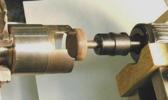
sharp. Now see the end-view sketch, and
the photo. A diamond-grit
mounted-point in a pneumatic �die grinder� (Harbor Freight, $20ish!) as you see
can be fastened to the lathe�s tool-post with wood bits and a clamp as you can
see here. Then the lathe�s compound hand wheel, cross-feed hand wheel, and manual rotation of the lathe-chuck to the
correct position can locate the O.D. of that mounted point (about 1�� O.D.)
exactly where it should be� see the End View sketch. Then horizontal-movement with the lathe�s Z-axis (aka
longitudinal feed) hand wheel does the grind, the crossfeed being moved ONE mil
per �in-out�. This little mounted point
you see was $37 from Enco.
Then this must be
next �precision-ground�. This can
actually be done �at home� if one uses a bit of imagination, and is very, very
cheap, like me! The O.D.,
face-surfaces, and �cutting ends� of the carbide can be reached with a
diamond-wheel in the mill as above, with the shank of the �plug-cutter� held in
the appropriate 5C collet in a square collet-fixture (hex, if a 3-tooth
cutter). This, then, leaves only the
inside-edges of the carbide teeth needing grinding, to provide a
clearance-angle for the cut, and to make that more important cutting-edge very
sharp. Now see the end-view sketch, and
the photo. A diamond-grit
mounted-point in a pneumatic �die grinder� (Harbor Freight, $20ish!) as you see
can be fastened to the lathe�s tool-post with wood bits and a clamp as you can
see here. Then the lathe�s compound hand wheel, cross-feed hand wheel, and manual rotation of the lathe-chuck to the
correct position can locate the O.D. of that mounted point (about 1�� O.D.)
exactly where it should be� see the End View sketch. Then horizontal-movement with the lathe�s Z-axis (aka
longitudinal feed) hand wheel does the grind, the crossfeed being moved ONE mil
per �in-out�. This little mounted point
you see was $37 from Enco.
For
this kind of grind, I did perhaps ten passes on one tooth, then turned
the chuck 180�, then ten passes on the other, alternately, so any �wheel wear�
did not particularly accumulate on just one of the two teeth. Common sense kinda thing.
The Bending Strength of Tubing
by Dick Kostelnicek
- HMSC Member
 From
experience we know that the stiffness or bending strength of tubing can be a substantial
fraction of that for a solid cylindrical bar of equal diameter. Some time ago I made an 18-in.
slip
roll and decided to use 2-in. schedule-80 pipe instead of solid
bar for the rolls. The saving in weight, and thereby the cost, was substantial. But,
how much did I sacrifice in the bending strength of the rolls?
From
experience we know that the stiffness or bending strength of tubing can be a substantial
fraction of that for a solid cylindrical bar of equal diameter. Some time ago I made an 18-in.
slip
roll and decided to use 2-in. schedule-80 pipe instead of solid
bar for the rolls. The saving in weight, and thereby the cost, was substantial. But,
how much did I sacrifice in the bending strength of the rolls?
The drawing at the left illustrates a tube roll with outer diameter D and radius R. The roll is supported only at the ends. For my slip roll, I used radial ball bearings. The wall thickness is T and length is L. I determined the deflection Y for a force F applied at the center of the roll. Now, what is important here is the deflection of a tube roll compared to what it would be for a more substantial solid bar having equal length L and diameter D.
 The left
scale on the graph shows the ratio of the deflection of
the tube to that of a solid bar as the percentage of wall
thickness, 100 T / R, varies. The right scale indicates the tube's
percentage weight of a solid bar. Three pipe thickness are referenced on the
graph; schedule-40, 80, and 160. The schedule-80 pipe that I used deflects only 1.8 times, 80% more, but
weighs just 33% as much as the solid bar. The table below shows some of
the characteristics of
the common forms of 2-in. (actual OD = 2.375 in.) steel pipe.
The left
scale on the graph shows the ratio of the deflection of
the tube to that of a solid bar as the percentage of wall
thickness, 100 T / R, varies. The right scale indicates the tube's
percentage weight of a solid bar. Three pipe thickness are referenced on the
graph; schedule-40, 80, and 160. The schedule-80 pipe that I used deflects only 1.8 times, 80% more, but
weighs just 33% as much as the solid bar. The table below shows some of
the characteristics of
the common forms of 2-in. (actual OD = 2.375 in.) steel pipe.
Since most of the things that I bend into a curve are small in size, 1000
pounds is the maximum force ever used on my rolls. The table shows the actual deflection
of 4.7 mills at the roll's center, an insignificant amount. This is
just 80% more than for a solid bar. I feel that I made the right decision to
employ
the lighter schedule-80 pipe rather than solid rod for the rolls.
|
Schedule |
Wall Thickness |
Weight |
Deflection |
Actual Deflection |
|
40 |
13 |
24 |
2.3 |
0.0061 in. |
|
80 |
18 |
33 |
1.8 |
0.0047 |
|
160 |
29 |
50 |
1.3 |
0.0035 |
How the calculations were made: The deflection of a beam supported at its ends with a central point load is Y = (F L^3 ) / (48 E I), where E is the modulus of elasticity, 30000000 lb. / in.^ 2, and I is the moment of inertia. The moment of inertia for a hollow cylinder is 3.14 (D^4 - d^4) / 64. These formulas can be found in Design of Weldments by the Lincoln Electric Co. Properties of American National steel pipes can be found in the Machinery's Handbook. My thanks to P. M. Shah who pointed me in the direction of the beam bending formulas.
|
The next meeting will be held on Saturday January 11, 2003 at the Collier Library 6200 Pinemont, Houston, TX at 1:00 p.m. Bring along a work in progress to show. Visit Our Web Site |
 |
Right click below then select [Save
Target As...]
From Netscape select [Save Link As..]
Microsoft
Word version of this newsletter 221 KB