Volume 9, No 6 - Jun, 2004
|
|
Volume 9, No 6 - Jun, 2004 |
|
|
|
|
|
| President - |
Vice President - |
||
| Treasurer - |
Secretary - |
|
|
| Webmaster - |
Editors - |
||
| Founder - |
SIG Coordinators - |
Statement of Purpose
Membership is open to all those interested in machining metal and tinkering with machines. The club provides a forum for the exchanging of ideas and information. This includes, to a large degree, education in the art of machine tools and practices. Our web site endeavors to bring into the public domain written information that the hobbyist can understand and use. This makes an organization such as this even more important.Regular Meeting
 Collier Library, Houston Texas, 1:00 p.m., May
8, 2004, Tom Moore, President presiding. 28 members were present. Don
Foster auctioned off a heat treating furnace and a drill motor holder that acts
like a mini drill press for the club's financial benefit. Dick Kostelnicek had
the winning bid on the furnace and Dean Eicher got the holder.
Collier Library, Houston Texas, 1:00 p.m., May
8, 2004, Tom Moore, President presiding. 28 members were present. Don
Foster auctioned off a heat treating furnace and a drill motor holder that acts
like a mini drill press for the club's financial benefit. Dick Kostelnicek had
the winning bid on the furnace and Dean Eicher got the holder.
Election of club officers will be held at the next meeting. If you want to
run for an office, raise you hand during the elections.
Business Meeting
Minutes are sent via email or regular mail to club members.
Presentation
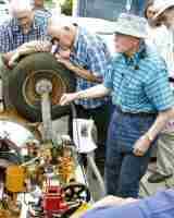


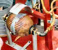
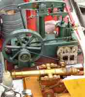
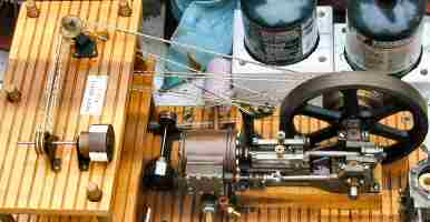
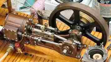
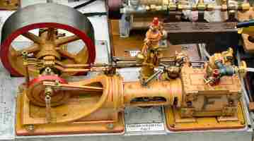
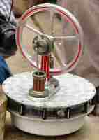
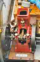
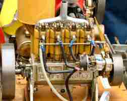
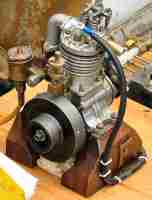
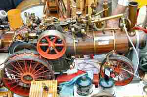
Don Foster showed off his many steam and gas engines built over many years.
Don has them permanently mounted for display on a trailer together with appropriate loads
on many of the engines. All were supplied with compressed air from a built-in
manifold on the trailer. Don's talk and demonstration was carried out in the
parking lot of the usual meeting place.
Special Interest Groups Activity
Novice Sig
The novice group reviewed the Cooper Tools tape and a short home video of making a part on Rich Pichler's old leather belt driven lathe. The lathe operations illustrated are as follows: Turning using a three jaw chuck and a dead center; Parting (cutting-off); Drilling on a lathe; Tapping on lathe; Mandrel turning using a tap as a mandrel, lathe dog and a slotted face plate; and Cutting threads on a lathe. Next time, there is no specific subject for the novice group unless another club member comes up with an idea that would be of interest to the novices.
Casting Sig
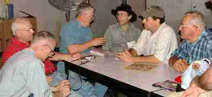 The
casting sig sat around and told "war" stories" about their casting
exploits.
The
casting sig sat around and told "war" stories" about their casting
exploits.
Show and Tell
Jan Rowland showed his oscillating steam engine that he made on a "dare" without plans and from pieces of metal laying around his shop. |
Dick Kostelnicek showed a hold down that safely clamps sheet metal onto a wood base for drilling on a drill press. with T-slots. He made the clamp base, T-nut and bolt for a store bought clamp. |
Featured Article
Drill Press Vise
Clamps
by J. R. Williams
- HMSC Member
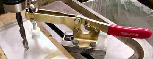
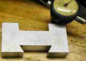
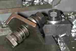 A secure method of clamping the vise to the drill press
table is necessary on my 20 inch unit. Any work not secured can be placed in a sideways orbit. After using clamps and step blocks from the
mill for a while, I decided there had to be a better way. The clamps
are custom made to fit my vise
using a standard forged T-bolt and a spherical face nut. I machined the matching spherical
washer. The clamp is a section of Ľ-in. x 2-1/2-in. steel angle milled with the short
leg the same height as the base of the vise. The overall length is 2-1/2
inches. Under the clamp I have added a
spring and a centering washer. The
washer keeps the spring from catching in the table slot.
A secure method of clamping the vise to the drill press
table is necessary on my 20 inch unit. Any work not secured can be placed in a sideways orbit. After using clamps and step blocks from the
mill for a while, I decided there had to be a better way. The clamps
are custom made to fit my vise
using a standard forged T-bolt and a spherical face nut. I machined the matching spherical
washer. The clamp is a section of Ľ-in. x 2-1/2-in. steel angle milled with the short
leg the same height as the base of the vise. The overall length is 2-1/2
inches. Under the clamp I have added a
spring and a centering washer. The
washer keeps the spring from catching in the table slot.
Lathe Indicator
Holder
by J. R. Williams
- HMSC Member
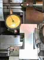
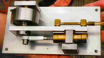
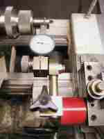
 An easy to use method of holding a small dial indicator
using the Aloris style tool post system is shown in the photos. Many machinists use a magnetic indicator
holder and attach it to the tool post or the compound, but I find there is a
big problem with the pick up of small chips. The base unit is a ľ
in. section of aluminum plate with a milled dovetail slot for
the tool post mount. The unit is
2-7/8 in. long x 1-1/2 in. wide. The width
of the slot is determined by using two dowel pins and the dial calipers to
measure the distance between the dowels with the pins contacting the taper
section and the bottom of the slot. See the HMSC
newsletter December 2002 article on Measuring Dovetails for details. The indicator is held to the
aluminum base with a hollow stud and a socket head cap screw. The clamp assembly allows the indicator to
be adjusted to the center line and used in the position shown in the photo or
rotated to check the face of a part in the chuck. The indicator used is an old Federal unit with a total dial
indication of 0.010 and small divisions of 0.0001. The rectangular cut-out was already in the material and serves
no purpose. The unit has served me
well for over 20 years and only requiring the indicator point to be
straightened a couple times.
An easy to use method of holding a small dial indicator
using the Aloris style tool post system is shown in the photos. Many machinists use a magnetic indicator
holder and attach it to the tool post or the compound, but I find there is a
big problem with the pick up of small chips. The base unit is a ľ
in. section of aluminum plate with a milled dovetail slot for
the tool post mount. The unit is
2-7/8 in. long x 1-1/2 in. wide. The width
of the slot is determined by using two dowel pins and the dial calipers to
measure the distance between the dowels with the pins contacting the taper
section and the bottom of the slot. See the HMSC
newsletter December 2002 article on Measuring Dovetails for details. The indicator is held to the
aluminum base with a hollow stud and a socket head cap screw. The clamp assembly allows the indicator to
be adjusted to the center line and used in the position shown in the photo or
rotated to check the face of a part in the chuck. The indicator used is an old Federal unit with a total dial
indication of 0.010 and small divisions of 0.0001. The rectangular cut-out was already in the material and serves
no purpose. The unit has served me
well for over 20 years and only requiring the indicator point to be
straightened a couple times.
Magnetic
Lathe Indicator Holder
by Dick Kostelnicek - HMSC Member
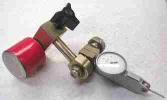 My
lathe indicator holder has grown in complexity over the years to have two swivel-sliding
and one rotary joint. That is probably over kill, but this is an avocation and
not a job for me. It is held to the side of the toolholder mounted in an Aloris
style holder by the red round pot magnet. I don't find chips getting in
the way of the magnet, but when they do, they can be removed easily with a piece
of sticky masking tape. When not in use, I stick a piece of steel
(keeper) to the magnet in order to prevent picking up magnetic particles. The
one advantage of the magnetic base is that it serves as another rotary-sliding
joint, as if I needed more flexibility. The holder's
body is made from German Silver (not real silver nor German). I just happened
to have some on hand, and found it to be non magnetic and a very tough alloy
to machine.
My
lathe indicator holder has grown in complexity over the years to have two swivel-sliding
and one rotary joint. That is probably over kill, but this is an avocation and
not a job for me. It is held to the side of the toolholder mounted in an Aloris
style holder by the red round pot magnet. I don't find chips getting in
the way of the magnet, but when they do, they can be removed easily with a piece
of sticky masking tape. When not in use, I stick a piece of steel
(keeper) to the magnet in order to prevent picking up magnetic particles. The
one advantage of the magnetic base is that it serves as another rotary-sliding
joint, as if I needed more flexibility. The holder's
body is made from German Silver (not real silver nor German). I just happened
to have some on hand, and found it to be non magnetic and a very tough alloy
to machine.
The War on Error - Rules
by Vance Burns - HMSC Member
Lately, I've been working on a project four times larger than my precision rule and seemed to be making a lot of careless mistakes. I'm a tiny bit anal about checking thrice - cutting once and this error spree was unsettling. After much self doubt and exhaustive checking, I realized my collection of dated measuring instruments had seen better days; anticipating the joy of another tool purchase, I decided it was time to upgrade.
Though my shopping list was quite long, initially I purchased a few combination squares. Not the big buck variety, but I expected something serviceable. Checking them first at the tool store, the devices looked fine (stores have lousy lighting) and I anticipated doing more research once at home. Surprise! The rule’s linear increments are off; and the sides of the rule are not parallel! One rule has sheared ends, fish-mouth on one and a bevel on the other. The second rule is nearer to acceptable, both being of the same brand. Most machinists I know at least try to produce things accurately; these were produced by accountants. I've got to get better glasses.
Looking up measuring standards on the web was enlightening. Many manufacturers do not list tolerances or degree of accuracy, yet claim to "... meet Federal specifications for accuracy". Baited, I took to uncovering the government standards. The standard wonks have their own website, the National Institute of Standards & Technology; www.NIST.gov.
Once I dug through the layers, I was surprised at how liberal the "standards" are for measuring devices. How liberal you ask? The 1994 changes for "measuring devices" now permit a manufacturing deviation of +/- 3/16 @ six feet. The NIST'etists are a bit tougher on "tape measures", the type used by surveyors. These tapes (aka "chain") are held to 3/16 at 80 feet... wouldn't want to negatively impact property taxes.
If the measuring instruments you purchase are not certified, or not manufactured in areas influenced by the NIST, there is room for deviation. Also note, these are specifications, not the same as a tool with a certification. One is a suggestion, the other a tested standard.
Speaking of tape, a few months ago, the Cooper rep came to the club and did a fine presentation, and I was impressed that he would note the difference in accuracy between their import and domestic items. I was enamored with the domestic Cooper Quickread tape. Sure enough, I bought one that week, and compensating for the variations inherent in the tape hook; it was exactly 3/16 off at the six foot mark. The next one was better.
I poked around on a few websites and found that this is a topic on a couple of forums. One end-user’s company rejects as much as 5% of big-name retractables, and up to 3% of the hard rules purchased. They didn't mention brands, but in the price strata they mentioned, there are only a few players.
Check your latest tool catalogs and notice how few give tolerance information for measuring equipment. If you do surf the web for sellers of these items, note that the information is nearly nonexistent.
|
Visit Our Home Page at |
 |
Right click below then select [Save
Target As...]
From Netscape select [Save Link As..]
Microsoft
Word version of this newsletter 196 KB