Volume 8, No 11 - November 2003
|
|
Volume 8, No 11 - November 2003 |
|
|
|
|
|
| President - |
Vice President - |
||
| Treasurer - |
Secretary - |
||
| Webmaster - |
Editors - |
||
| Founder - |
SIG Coordinators - |
Statement of Purpose
Membership is open to all those interested in machining metal and tinkering with machines. The club provides a forum for the exchanging of ideas and information. This includes, to a large degree, education in the art of machine tools and practices. Our web site endeavors to bring into the public domain written information that the hobbyist can understand and use. This makes an organization such as this even more important.Regular Meeting
 Collier
Library, Houston Texas, 1:00 p.m., September 13, 2003.
Collier
Library, Houston Texas, 1:00 p.m., September 13, 2003.
Dues for 2004 are past due. See John Hoff - treasurer, and pay your $15.
Questions about a club field trip were asked. If anyone can arrange a trip to a local manufacturer or shop, please contact Tom Moore - president.
For the November "Show & Tell" portion of the meeting,
bring those tools that you just had to buy but have never been useful.
As suggested by Tom Moore. Art Volz, just one shopping
cart full - please!
Business Meeting
Minutes are sent via email or regular mail to club members.
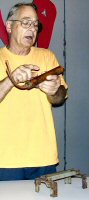
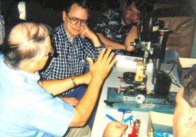
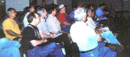
Presentation
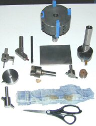 Fly cutters were the topic for the group
presentation. Members brought their favorite fly cutters. Each described
their use and passed them around for "touch and feel" by the
members. Most were home made. The "biggest-one" award goes to Dick
Kostelnicek. His has 4-1/2-in. brazed carbide cutters and "can really
throw some hot chips around the shop". Ed Gladkowski gets the award
for "fly cutter having the best finish" as compared to "fly
cutter that gives the best finish". Ed does everything on a shaper! Enough
said. Joe Williams uses a face mill tool that holds indexable carbide
chips. He removes all but one chip. Leo Reed uses a drill press
as a vertical mill. Most of the stuff he makes is in aluminum and brass,
which is some comfort to the spindle bearings in his drill press. Art Volz
brought a scissors and cut the fly from his pants. Yes Art!
Indeed we did say bring your "fly Cutter". We'll have
to give Art more explicit instructions in the future.
Fly cutters were the topic for the group
presentation. Members brought their favorite fly cutters. Each described
their use and passed them around for "touch and feel" by the
members. Most were home made. The "biggest-one" award goes to Dick
Kostelnicek. His has 4-1/2-in. brazed carbide cutters and "can really
throw some hot chips around the shop". Ed Gladkowski gets the award
for "fly cutter having the best finish" as compared to "fly
cutter that gives the best finish". Ed does everything on a shaper! Enough
said. Joe Williams uses a face mill tool that holds indexable carbide
chips. He removes all but one chip. Leo Reed uses a drill press
as a vertical mill. Most of the stuff he makes is in aluminum and brass,
which is some comfort to the spindle bearings in his drill press. Art Volz
brought a scissors and cut the fly from his pants. Yes Art!
Indeed we did say bring your "fly Cutter". We'll have
to give Art more explicit instructions in the future.
|
Dick Kostelnicek |
Ed Gladkowski |
Joe Williams |
Leo Reed |
Show and Tell
|
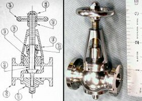
Dick Kostelnicek brought the throttle valve he made from stainless steel and brass for his Corliss steam engine. He also showed how to card or clean hand files by bead blasting |
|
on a spin index. It has 25 graduations for marking a dial handle. He added also locations for 50 and 100 holes "just in case". |
|
Art Volz brought an antique hand operated model scroll saw. |
Tony Burnett described how he hand welds the seams on parts for his 1940's Kugle Wagon using a metal guide frame |
Doug Chartier showed the tail gate hinge for a mid 50's vintage car that he made for a request that came to the club over the Internet. |
Tom Moore brought a number of gas torches. He actually had a bigger one than that shown by Ed Gladkowski at the last meeting. |
Special Interest Groups Activity
|
Nothing went on concerning Casting Sig. More of a social meeting. |
No activity this month. |
Dennis Cranston talked about his small mill. |
Featured Articles
A Rotary Sine Bar for the
Lathe
by Ed Gladkowski - HMSC Member
 I
needed to index 125 divisions on a feed-dial for a project, and decided to make
an indexing attachment for my old faithful 9” model B South Bend lathe. I’d
read many accounts over the years of different methods of lathe indexing, but
none were quite what I wanted. The main points I was looking for were:
(1) an easily-mounted attachment that would require no alternations
at all to my long-suffering old lathe; (2) a way of locking the spindle
at each division without relying on an indexing pin or worm gear; and (3) easily
set up for any angular indexing or number of divisions without having to make
new index plates.
I
needed to index 125 divisions on a feed-dial for a project, and decided to make
an indexing attachment for my old faithful 9” model B South Bend lathe. I’d
read many accounts over the years of different methods of lathe indexing, but
none were quite what I wanted. The main points I was looking for were:
(1) an easily-mounted attachment that would require no alternations
at all to my long-suffering old lathe; (2) a way of locking the spindle
at each division without relying on an indexing pin or worm gear; and (3) easily
set up for any angular indexing or number of divisions without having to make
new index plates.
After ruminating awhile, I thought of adapting the sine bar principle, along with sort of a disc brake, and came up with the unit described in this article. No add-on attachment is perfect, but this one does what I was looking for and is accurate if given care in making and use.
 No
dimensions are given as it is the principle of the device that matters and you
can make it to suit yourself, your lathe, and your methods of working. Sine
bars are often made with 5” or 10” centers, which seems proportionate for my
lathe, but you could go larger or smaller for a bigger or smaller machine. With
a ten dollar pocket calculator, you could use 7.684” centers if you want to.
Just multiply the sine of the angle you want by your sine bar center-to-center
dimension (which becomes your constant) to get the required spacer block thickness.
As an example, to get 125 equal divisions with a 5” sine bar: 360
degrees divided by 125 equals 2.88 degrees per division. The sine of 2.88
degrees is .05024. Multiplying by 5 (constant for a 5” sine bar) and rounding
off to 4 places gives .2512” as the required thickness of the spacer block.
As for the spacer blocks themselves, workshop-grade gage blocks are fairly
inexpensive today, or you can use adjustable parallels, ground tool bits
and feeler gages, or even a hand-filed block.
No
dimensions are given as it is the principle of the device that matters and you
can make it to suit yourself, your lathe, and your methods of working. Sine
bars are often made with 5” or 10” centers, which seems proportionate for my
lathe, but you could go larger or smaller for a bigger or smaller machine. With
a ten dollar pocket calculator, you could use 7.684” centers if you want to.
Just multiply the sine of the angle you want by your sine bar center-to-center
dimension (which becomes your constant) to get the required spacer block thickness.
As an example, to get 125 equal divisions with a 5” sine bar: 360
degrees divided by 125 equals 2.88 degrees per division. The sine of 2.88
degrees is .05024. Multiplying by 5 (constant for a 5” sine bar) and rounding
off to 4 places gives .2512” as the required thickness of the spacer block.
As for the spacer blocks themselves, workshop-grade gage blocks are fairly
inexpensive today, or you can use adjustable parallels, ground tool bits
and feeler gages, or even a hand-filed block.
Any division much over 30 degrees starts to need a fairly tall spacer block (30 degrees on a 5” bar needs 2 ˝ “) so you might find it convenient to index in steps, say three 30 degree steps to get 90 degrees.
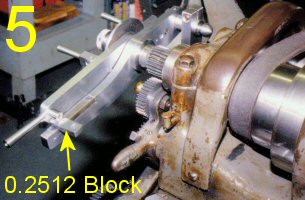
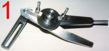
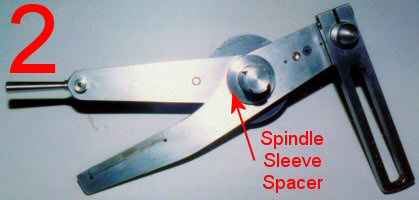 Looking
at the pictures, #1 and #2 show the attachment from its front (as viewed from
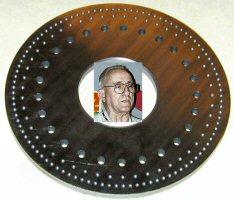
rear of lathe) and back sides. The disc for the brake was cut out of 1/8”
thick hot-rolled mild steel, using a big hole saw. The edge was “cleaned
up”, but the faces were left as-is for a better grip of the clamps under the
toggle handles.
Looking
at the pictures, #1 and #2 show the attachment from its front (as viewed from
rear of lathe) and back sides. The disc for the brake was cut out of 1/8”
thick hot-rolled mild steel, using a big hole saw. The edge was “cleaned
up”, but the faces were left as-is for a better grip of the clamps under the
toggle handles.
There is a hardened plate inlet into the end of the stationary arm, that the 3/8” diameter hardened sine bar pin bears against. The top face of this plate is 3/16” below the centerline of the spindle-arbor so that when the pin is touching the plate, the centerlines coincide horizontally. The distance between the vertical centerlines of the sine bar pin and spindle arbor (5” in this case) is the constant used to multiply the sine of the required angle to get the thickness of spacer block needed for a particular indexing job.
Both the sine bar and stationary arm are made out of 3/8” thick 1018 cold rolled mild steel. Both have oil-impregnated bronze bushings for the spindle-arbor, which rotates in the stationary arm while the sine bar rotates on it.
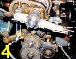
The bracket with the long slot clamps to the lathe change gear quadrant, as shown in picture #4, by means of a T-bolt and the nut with the 2 ball-end handles. The upper end of the slotted bracket, in turn, clamps to the large pin which is press-fitted and pinned into the left end of the stationary arm.
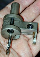
Picture #3 shows the unit taken apart. There is a small 3/8” thick block fastened to the stationary arm next to the spindle-arbor bushing, to take the thrust of the clamp plate on the disc brake.
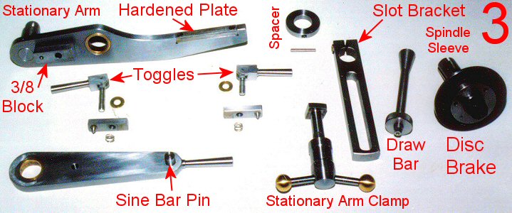
The toggles on the brake clamps have cam-shaped ends, so pulling them up “sets the brakes” with a single motion for convenience.
The spindle-arbor on the right has a split tapered bore where it fits into the lathe spindle and is tightened in place with the matching tapered drawbar. The disc for the brake is screwed with flat-head screws to a collar that is shrunk (some might prefer adhesives) onto the spindle-arbor; the collar and disc are also pinned together for security. The sine bar arm and stationary arm are held in place axially by the other collar shown between the slotted bracket and the end of the stationary arm. Originally, I used a Teflon washer between the sine bar and stationary arm to prevent rubbing. This proved too wobbly, and now I use a thin washer cut from phosphor bronze (brass would also work) shim stock between the arms and also under each collar.
 Picture
#4 shows the attachment mounted on the lathe, and #5 shows it from the back
with a homemade (filed) .2512” spacer block in operating position.
Picture
#4 shows the attachment mounted on the lathe, and #5 shows it from the back
with a homemade (filed) .2512” spacer block in operating position.
To use the attachment: (1) make sure power to the machine is disconnected and install the unit on the lathe. (2) Lock the stationary arm clamp to hold the spindle. (3) Raise the sine bar arm and bring it down snugly onto the required spacer, as shown in picture #5, then lock the sine bar brake clamp. (4) Release the stationary arm brake to free the lathe spindle, remove the spacer block, and using the sine bar handle, bring the pin on the arm down in contact with the plate on the stationary arm, thus rotating the lathe spindle for the first division. Now, lock the stationary arm brake clamp to hold the spindle. (5) Repeat steps 2, 3 and 4 for each division until the job is complete.
Once you get used to it, it’s much faster to do than to write. Like all repetitious jobs, you have to keep in mind what you’re doing, but it is certainly no worse than counting turns and remembering to shift the sector arms on a worm-type indexing rig
One last point; the rotary sine bar idea needn’t be confined to lathe use. Make an auxiliary spindle for it and it could be used for an index head on other machines. Or, turn it on end with a faceplate on top and use it for a rotary table. Or, mount one on a lead screw for precision linear location. There are lots of possibilities. As I said before, it is the principle that matters.
An Electric Gate Caster
by
Jan Rowland - HMSC Member
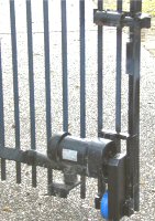 When
we moved into this present address in ‘85, this weld-fabricated gate over the
p-gravel drive was newish, and had only a rubber-tired caster to support the
free end. That caster was mounted on that bracket you can see under the left
end of the of the motor in left picture. Thus, to open/close the
gate before, one must go out in the rain and wrestle with the horrible iron
thing, hoping the neighbors don’t hear the epithets.
When
we moved into this present address in ‘85, this weld-fabricated gate over the
p-gravel drive was newish, and had only a rubber-tired caster to support the
free end. That caster was mounted on that bracket you can see under the left
end of the of the motor in left picture. Thus, to open/close the
gate before, one must go out in the rain and wrestle with the horrible iron
thing, hoping the neighbors don’t hear the epithets.
I very soon built a bolt-on motor-mount using a Graingers 60 RPM gear motor, with a 6” dia. rubber-tired caster-wheel connected to that motor with #35 sprocket chain. That single-phase motor lasted a whole year! — before it simply just quit for no discernable reason. Lucky we have three-phase power here (otherwise, I’d not have much home-shop machinery!), and Graingers did offer a same-frame-size 3-Ř gear-motor——works MUCH better, and is still going fine after seventeen years.
 But
I'm guessing there’s about 400 lb. of weight on that end of the gate, to take
half the load off the hinges on the other end, so the tire on that caster-wheel
on the p-gravel takes a beating. After seventeen years opening and closing
at least once per day, the rubber finally became un-vulcanized from the cast
aluminum wheel, and, well, you get the picture!
But
I'm guessing there’s about 400 lb. of weight on that end of the gate, to take
half the load off the hinges on the other end, so the tire on that caster-wheel
on the p-gravel takes a beating. After seventeen years opening and closing
at least once per day, the rubber finally became un-vulcanized from the cast
aluminum wheel, and, well, you get the picture!
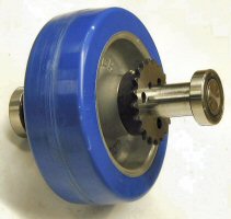
Grainger still sells that same replacement-wheel, but now, they also offer a polyurethane-tire version with a 1400 lb. rating, specified “for use over rough surfaces”, which this certainly is! So, I used the car-jack to raise that free end a half-inch or so, and removed the old shaft and wheel-assembly, so I could rebuild it as you see in Fig. 2. I had dutifully used grease on the chain, so the sprocket was undamaged, and I could simply face and tap the new wheel’s hub and screw the old sprocket on it.
Though the old sealed ball-bearings were still functioning “good enough”, they were not “good as new”, so I replaced ‘em with fresh ones as you see, hopefully to preclude replacing any of that again in many years. I’m too lazy to wanna even THINK about it!
Presently, I operate the motor by a couple of DPDT relays, with big contacts and wired so that only one is energized at the time. Each relay is wired to either open or close the gate. I have a switchbox in the garage, at other end of drive, and intend to wire-up a Genie radio controller.
|
Visit Our Web Site |
 |
Right click below then select [Save
Target As...]
From Netscape select [Save Link As..]
Microsoft
Word version of this newsletter 462 KB