Volume 8, No 10 - October 2003
|
|
Volume 8, No 10 - October 2003 |
|
|
|
|
|
| President - |
Vice President - |
||
| Treasurer - |
Secretary - |
||
| Webmaster - |
Editors - |
||
| Founder - |
SIG Coordinators - |
Statement of Purpose
Membership is open to all those interested in machining metal and tinkering with machines. The club provides a forum for the exchanging of ideas and information. This includes, to a large degree, education in the art of machine tools and practices. Our web site endeavors to bring into the public domain written information that the hobbyist can understand and use. This makes an organization such as this even more important.Regular Meeting
 Collier
Library, Houston Texas, 1:00 p.m., September 13, 2003.
Collier
Library, Houston Texas, 1:00 p.m., September 13, 2003.
The Sept. meeting featured the
various kinds of lathe radius attachments used by club
members. For the October meeting we will
be having a FLY CUTTER ROUND-UP. So, bring them to the meeting, preferably
with pictures of their use.
Member News
 John
Korman, the founder of our club, died September 19, 2003. A article, Houston
Home Metal Shop Club Origins, written by Keith Mitchell, appeared in the
September, 2002 club newsletter. It describes how John brought together metal
workers and tinkerers in the Houston, TX area in 1996. John is also the author of
many HMSC newsletter articles.
John
Korman, the founder of our club, died September 19, 2003. A article, Houston
Home Metal Shop Club Origins, written by Keith Mitchell, appeared in the
September, 2002 club newsletter. It describes how John brought together metal
workers and tinkerers in the Houston, TX area in 1996. John is also the author of
many HMSC newsletter articles.You know, the older we get the more we know, and understand the vile work
of the dark specter. John's good work will live on, in his children, and his
dreams. Each time we meet, we celebrate ideas and the love of the craft that
John knew so well. What John helped create is a living thing, and the unmeasured
success of what we now enjoy is tribute to John's vision and dedication. As
a former President of the club, I interacted with John on many occasions, and
can surely say that John had a passion for the club and it's success. We
will miss him, but once a month, on the second Saturday, we will talk the talk
he loved to hear, recount the experiences he too lived, and relish the gift
he left us. - Vance Burns
Business Meeting
Minutes are sent via email or regular mail to club members.
Presentation
|
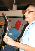
J. Kelly Mowry, President of Gull Industries, spoke about production metal plating processes including, precision dense chrome, electroless nickel, high production nickel, vapor honing, and ion beam coatings. |
|
Show and Tell
Doug Chartier showed some large Aloris tool holders and a collet stop with an expanding cam that grips the inner wall of the spindle's through hole. |
|
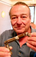
Art Volz brought one of the toys we all played with as children. It's a U-joint made from bent rods. |
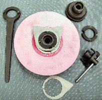
 Ed
Gladkowski brought the silicon bronze casting, drag plate and core pattern for
a pulley for a model steam engine he is building.
Ed
Gladkowski brought the silicon bronze casting, drag plate and core pattern for
a pulley for a model steam engine he is building.
Editor Note: Oops! This picture
was left out of the September newsletter.
Computer Numerical Control SIG
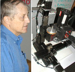 The CNC SIG looked at Dennis Cranston's Sherline CNC Machining
Center. The unit is based on a CNC ready Sherline and 187 oz-in steppers and
a Xylotex driver. It used a Mini-ITX PC Mother board running XP
Pro. The control program is currently MACH1. - Dennis Cranston
The CNC SIG looked at Dennis Cranston's Sherline CNC Machining
Center. The unit is based on a CNC ready Sherline and 187 oz-in steppers and
a Xylotex driver. It used a Mini-ITX PC Mother board running XP
Pro. The control program is currently MACH1. - Dennis Cranston
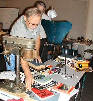
Novice Sig
 The
Novice Sig worked on hole drilling. They brought a desktop drill press and practiced
drilling holes in the metal plates that they scribed and center punched during
the Sept. meeting. Some of the drill types that they discussed were: Silver
& Demming (reduced shank), Center Drills, Counter Sinks, Spur Point
(sheet metal drills).
The
Novice Sig worked on hole drilling. They brought a desktop drill press and practiced
drilling holes in the metal plates that they scribed and center punched during
the Sept. meeting. Some of the drill types that they discussed were: Silver
& Demming (reduced shank), Center Drills, Counter Sinks, Spur Point
(sheet metal drills).
Featured Articles
|
|
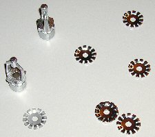
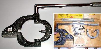
Joe Williams brought in his factory-made and home-made versions of the traditional radius attachment. The bit rotates in the horizontal plane. The upper tool shown is set up to cut a ball. By reversing the bit in the swinging U-shaped arm, it also can cut an inside radius (dish). The home-made weldment tool, shown in the lower photo, cuts an inside curve. |
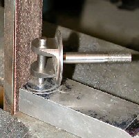
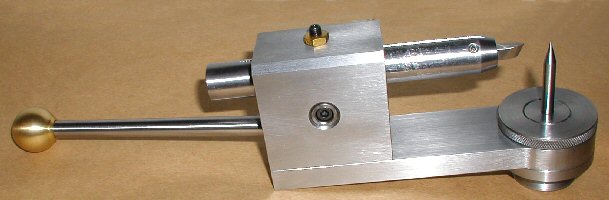
The right photo shows a ball turning attachment that rotates about the horizontal axis that is perpendicular to the lathe's axis. The bit rotates about a 1-in. shank that is supported by a horizontal 1-in. Aloris style boring bar holder. Once the height of the shank's center is set to that of the lathe's axis, the attachment can be removed and subsequently reattached to the toolpost and remains on center. The ball radius is determined by adjusting the offset slide attached to the shank. A box wrench is used to turn the tool around the ball being cut. |
|
Remember to bring your FLY CUTTERs to the next meeting's tool roundup!
Radius Grinding
Fixture
J. R. Williams
- HMSC member
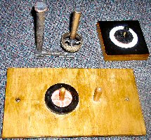
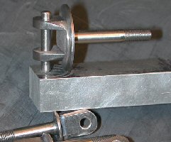 The project was to
machine a quantity of special hinge bolts, for a WWI replica airplane, with a
uniform 1/4 inch radius on the ends of the bolts. The first idea was to hand grind the radius to a scribed line,
but I soon gave up on that idea and went for the fixture in the photo. I used a base of 3/4 inch aluminum bar stock
and drilled a hole thru and reamed a little over half way for a 3/16 diameter
dowel pin that was pressed in place. To
grind the radius, I used my 1 inch wide belt sander. The part on the fixture was pressed up against the belt and the
part was rotated while holding the fixture steady. The result was a uniform radius on the parts. The radius part of the project was the easy
part of the project. The large part,
with the two sections, was made from a 1-1/4 inch diameter bar stock of 4130
steel with the threaded section 1/4 inch in diameter. Fabricating a fixture to machine a radius
does not have to be complicated.
The project was to
machine a quantity of special hinge bolts, for a WWI replica airplane, with a
uniform 1/4 inch radius on the ends of the bolts. The first idea was to hand grind the radius to a scribed line,
but I soon gave up on that idea and went for the fixture in the photo. I used a base of 3/4 inch aluminum bar stock
and drilled a hole thru and reamed a little over half way for a 3/16 diameter
dowel pin that was pressed in place. To
grind the radius, I used my 1 inch wide belt sander. The part on the fixture was pressed up against the belt and the
part was rotated while holding the fixture steady. The result was a uniform radius on the parts. The radius part of the project was the easy
part of the project. The large part,
with the two sections, was made from a 1-1/4 inch diameter bar stock of 4130
steel with the threaded section 1/4 inch in diameter. Fabricating a fixture to machine a radius
does not have to be complicated.
A Sea Story
by
an anonymous HMSC member
A few wars ago in 1968, my old destroyer was back in the south China sea off Vietnam after some quick repairs in the Subic Bay (Philippines) shipyard, when a little problem came up. The steam turbine-driven main condenser water circulating pump in the forward engine room wasn’t working too good (to put it mildly). The pump end had a water-lubricated split bronze sleeve bearing about 14 inches long, 3 inches ID by 4 inches OD . The 1/2-inch thick bearing walls were perforated with a bunch of 3/8-inch holes for water to cool and lube the shaft. The two halves of the split bearing were aligned by four dowel pins in the mating faces.
Maybe because things were kind of busy then, the shipyard workers had reassembled the bearing with only two dowels engaged, so that each half of the sleeve overhung the other by about three inches on each end. Somehow, they managed to get it back in the pump bearing housing which was also split, put the cover on, and slug up the nuts.
When the pump finally quit, it was torn apart and the mangled bearing found. When it had been bolted up, about 3 inches of each half had been bent diagonally outward by almost an inch. Since we had no spare bearings on board, it was fix it or leave our duty station and limp back to the yard.
Fletcher-class destroyers had a 16 inch lathe, a drill press, and a small workbench with a good heavy bench vise. The way we fixed the bearing was as follows:
The pump shaft was “miked” and a piece of brass bar stock turned between centers .004 inches oversize for running clearance, using the old rule of thumb “.001 inch of clearance per inch of shaft diameter plus .001 for luck.
Each bearing half was held in soft jaws in the bench vise and beat back into something like the original shape using the biggest (about 5 pound) rawhide mallet we had in the ship. Sounds extreme, but there was nothing to lose; it was no good as it was.
The two bearing halves were then fitted to the .004 inch oversize bar using Prussian blue, half-round files and finally scrapers. When it was as good as we could get it on the bore, the outside diameter was fitted into the pump housing again using blue, files and scrapers, while hanging upside down in the bilge through a hole in the engine room deck plates.
Not much more to add – the pump was reassembled (this time with all four bearing dowel pins aligned!), lit off and put on the line. It ran fine until we got back to the U.S.A. about six months later.
Maybe the moral is, you don’t always need elaborate equipment to do a job if it really has to be done.
|
Visit Our Web Site |
 |
Right click below then select [Save
Target As...]
From Netscape select [Save Link As..]
Microsoft
Word version of this newsletter 590 KB


 Tom
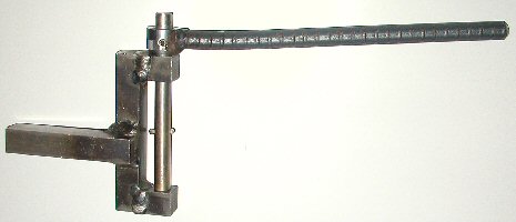
Moore's attachment rotates about the horizontal axis tthat is
perpendicular to the
lathe's axis. It attaches directly to the T-slots in his Myford
lathe's cross slide. The ball radius is set by moving the
bit holder's cross slide that is attached to the rotating shank.
Similar devices use a boring head to produce the offset in order
to change the ball radius.
Tom
Moore's attachment rotates about the horizontal axis tthat is
perpendicular to the
lathe's axis. It attaches directly to the T-slots in his Myford
lathe's cross slide. The ball radius is set by moving the
bit holder's cross slide that is attached to the rotating shank.
Similar devices use a boring head to produce the offset in order
to change the ball radius.