Volume 7, No 10 - October, 2002
|
|
Volume 7, No 10 - October, 2002 |
|
|
|
|
|
| President - |
Vice President - |
||
| Treasurer - |
Secretary - |
||
| Webmaster - |
Editors - |
||
|
|
|
SIG Coordinator - |
Membership Information
Membership is open to all those interested in machining metal and tinkering with machines. The purpose of the club is to provide a forum for the exchanging of ideas and information. This includes, to a large degree, education in the art of machine tools and practices. There is a severe shortage of written information that a beginning hobbyist can understand and use. This makes an organization such as this even more important.
Business Meeting
Minutes are sent via email or regular mail to club members.
Regular Meeting
Presentations
High-Speed Machining
by
Tom Wittenbach - TW Tool, Inc.
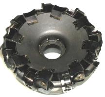

This is truly a look into the future of metal removal. An interesting hint discussed was to bevel the impact edge of an interrupted cut in order to reduce insert breakage. This technique should work with conventional carbide tooling. High-speed machining is the type of know-how which will keep us competitive in world markets.
Tom can be reached at 713 823-3308; twtool@wt.net; or TW Tool, Inc., P. O. Box
40156, Houston, TX 77240
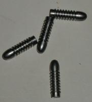
Making Your Own Bullets
by J.
R. (Joe) Williams - HMSC Member
Show and Tell
|
Joseph Scott showed an electronic edge finder which lights up on contact. "They're much easier to use than the mechanical types." He also showed a self-releasing tap head and a plastic drip bottle to direct lathe coolant. |
Ed Glaskowski showed his spider used to support irregular shaped objects in the center rest. For the gunsmith, this tool can center irregularly shaped gun barrels in a lathe. |
Whitney Rassback showed a Bosch electric hedge trimmer attachment for a European 220 V Bosch drill motor. Powerful stuff ! |
Metal Casting SIG
No activity this month.
Computer Numerical Control SIG
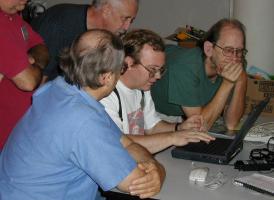 Dennis Cranston brought in a EMC controller
program. This program, developed under government sponsorship, provides
modern technology for small CNC controllers. It was designed to run under the
Linux operating system. The installation shown at the meeting was a BDI or Brain Dead
Install; not requiring previous Linux experience. The picture shows Gordon
Lawson demonstrating some easy steps to customize the program
installation. - by Dennis
Cranston
Dennis Cranston brought in a EMC controller
program. This program, developed under government sponsorship, provides
modern technology for small CNC controllers. It was designed to run under the
Linux operating system. The installation shown at the meeting was a BDI or Brain Dead
Install; not requiring previous Linux experience. The picture shows Gordon
Lawson demonstrating some easy steps to customize the program
installation. - by Dennis
Cranston
Featured Articles
Horizontal Cut-Off Bandsaw Tips
by Dick Kostelnicek - HMSC Member
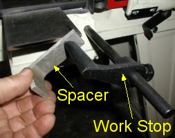 When
I make repeat cuts, I use the saw's work stop to set how far the work extends
beyond the blade. However, I also use a scrap of metal as a spacer
between the end of the bar being cut and the saw's work stop. Then, I tighten
the vise, remove the spacer, and complete the cut. The clearance,
provided by the spacer, prevents the drop (piece cut off) from jamming
between the blade and the work stop.
When
I make repeat cuts, I use the saw's work stop to set how far the work extends
beyond the blade. However, I also use a scrap of metal as a spacer
between the end of the bar being cut and the saw's work stop. Then, I tighten
the vise, remove the spacer, and complete the cut. The clearance,
provided by the spacer, prevents the drop (piece cut off) from jamming
between the blade and the work stop.
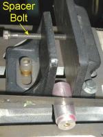 To
cut a piece that is too short to be adequately held in the saw's vise,
I run a 1/4-20 spacer bolt, that is threaded through the back of the movable
jaw, up against the fixed jaw. That way I don't have to search for just
the right thickness spacer to place in the other end of the vise.
To
cut a piece that is too short to be adequately held in the saw's vise,
I run a 1/4-20 spacer bolt, that is threaded through the back of the movable
jaw, up against the fixed jaw. That way I don't have to search for just
the right thickness spacer to place in the other end of the vise.
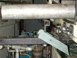
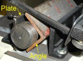 Sometimes
the piece being cut is just a scrap that is too short to be held in the saw's
vise. I extend the jaws by using a piece of angle and a flat
plate that provide a three point contact gripping the short piece to be cut. The moveable
jaw extension
plate has a threaded bolt at its back end (not seen) that contacts the crotch
in the angle so that the saw's jaws remain parallel when the vise is tightened.
Sometimes
the piece being cut is just a scrap that is too short to be held in the saw's
vise. I extend the jaws by using a piece of angle and a flat
plate that provide a three point contact gripping the short piece to be cut. The moveable
jaw extension
plate has a threaded bolt at its back end (not seen) that contacts the crotch
in the angle so that the saw's jaws remain parallel when the vise is tightened.
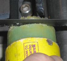 My
saw does not have a forced coolant-lubrication system. This creates a problem
only when I cut soft aluminum, which tends to cold weld itself in the blade's
gullets. The aluminum build up can be so great on a thick
cut that the tooth's set provides insufficient kerf and the blade
begins to drift to one side or the other. In order too prevent aluminum
buildup, I touch a bandsaw wax stick periodically to the blade's teeth. In fact, I prefer
to cut right through the stick's paper tube to a depth of 3/4 of the blade
width to apply wax to the teeth and wipe clean the sides of the blade.
My
saw does not have a forced coolant-lubrication system. This creates a problem
only when I cut soft aluminum, which tends to cold weld itself in the blade's
gullets. The aluminum build up can be so great on a thick
cut that the tooth's set provides insufficient kerf and the blade
begins to drift to one side or the other. In order too prevent aluminum
buildup, I touch a bandsaw wax stick periodically to the blade's teeth. In fact, I prefer
to cut right through the stick's paper tube to a depth of 3/4 of the blade
width to apply wax to the teeth and wipe clean the sides of the blade.
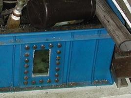
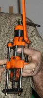
Personalizing a Bandsaw
by J.
R. (Joe) Williams - HMSC Member
|
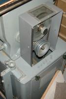
Modifications to my 7x12 in. Jet horizontal cut-off bandsaw:
|
|
|
|
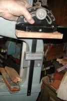
Modifications to my Delta 15 in. vertical bandsaw:
|
Square
Drive Crank from a Weldment
by Dick Kostelnicek - HMSC Member
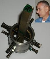
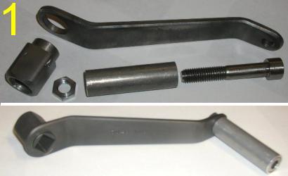 I
fabricated a 5/8 in. square drive crank from a machined weldment (welded
up from pieces). Figure 1 shows the crank's parts and finished assembly.
The square socket head was built-up from four flats welded together and then
machined on the outer surface. The finished head was silver brazed into a
1 in. dia. hole drilled in the big end of a bent arm. A rotating sleeve hand
grip was attached via a threaded hole in the small end of the arm using a 3/4 in. socket head cap screw and
jamb nut. The entire 8 in. long crank
was Parkerized ® - a hot dip chemical coating that prevents rusting.
I
fabricated a 5/8 in. square drive crank from a machined weldment (welded
up from pieces). Figure 1 shows the crank's parts and finished assembly.
The square socket head was built-up from four flats welded together and then
machined on the outer surface. The finished head was silver brazed into a
1 in. dia. hole drilled in the big end of a bent arm. A rotating sleeve hand
grip was attached via a threaded hole in the small end of the arm using a 3/4 in. socket head cap screw and
jamb nut. The entire 8 in. long crank
was Parkerized ® - a hot dip chemical coating that prevents rusting.
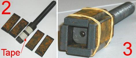 Figure
2 shows that the socket weldment consisted of four segments cut
from a 2 x 1/4 in. mild steel flat. The 3/4 in. wide segments were temporarily
secured around a mandrel with rubber bands, as shown in figure 3. The mandrel was
one of the square headed bolt shanks that will be eventually driven
by the crank. Two layers of masking tape was wrapped around the mandrel in
order to provide 0.008 in.clearance for a sliding fit between the finished
square socket and
the driven shanks.
Figure
2 shows that the socket weldment consisted of four segments cut
from a 2 x 1/4 in. mild steel flat. The 3/4 in. wide segments were temporarily
secured around a mandrel with rubber bands, as shown in figure 3. The mandrel was
one of the square headed bolt shanks that will be eventually driven
by the crank. Two layers of masking tape was wrapped around the mandrel in
order to provide 0.008 in.clearance for a sliding fit between the finished
square socket and
the driven shanks.
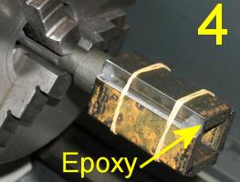 Small
dabs of quick
setting epoxy resin were used to tack the socket shells together in preparation
for welding. Figure 4 shows the mandrel being slowly turned in a lathe
while the epoxy cured. Rotating the weldment prevents the resin from sagging
or spreading
along the shell's seams. Figure
5 shows the shells being tack welded between the epoxy tacks. I tack weld such small
pieces in a sardine can filled with sand. The sand provides support for the
odd shaped weldment and prevents splatter from sticking to the surface of the
metal welding table. A long nose VISE-GRIP ® was used as an narrow
extension
clip for the large bronze ground clamp.
Small
dabs of quick
setting epoxy resin were used to tack the socket shells together in preparation
for welding. Figure 4 shows the mandrel being slowly turned in a lathe
while the epoxy cured. Rotating the weldment prevents the resin from sagging
or spreading
along the shell's seams. Figure
5 shows the shells being tack welded between the epoxy tacks. I tack weld such small
pieces in a sardine can filled with sand. The sand provides support for the
odd shaped weldment and prevents splatter from sticking to the surface of the
metal welding table. A long nose VISE-GRIP ® was used as an narrow
extension
clip for the large bronze ground clamp. 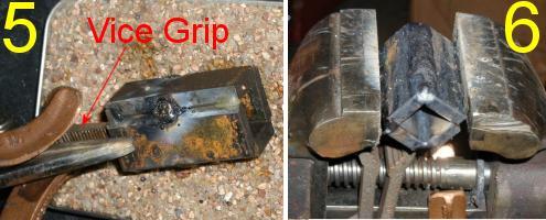 The weldment was cooled in water after each edge was tack welded in order to
prevent heat from softening of the epoxy positioning tacks.
The weldment was cooled in water after each edge was tack welded in order to
prevent heat from softening of the epoxy positioning tacks.
After tack wedling all four edges, the epoxy was removed and the seams were finished welded. Figure 6 shows the use of an old vise, that has been bolted to the metal welding table, to position small parts. All paint was stripped from the vise, thereby, providing a good electrical ground connection to small parts being held for welding
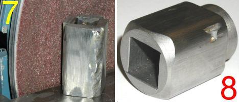 Figure
7 illustrates how I rounded over the corner weld beads using a disk
sander. Finally, figure 8 shows the square socket after being sandblasted inside
and finished turned on the outside.
Figure
7 illustrates how I rounded over the corner weld beads using a disk
sander. Finally, figure 8 shows the square socket after being sandblasted inside
and finished turned on the outside.
Now, I know that I could have purchased a torquing socket
for 5/8 in. square headed bolts, and then turned it to produce
an equally good part for the crank. But, sockets for square head bolts are not available at my local home improvement center. Besides, this is what
I do for entertainment Sunday evening. Lastly, I'm sure I'll be hearing
from the shaper buffs, about the merits of their machines in making square
holes.
|
The next meeting will be held on Saturday October 12, 2002 at the Collier Library 6200 Pinemont, Houston, TX at 1:00 p.m. Bring along a work in progress to show. Visit Our Web Site |
 |
Right click below then select [Save
Target As...]
From Netscape select [Save Link As..]
Microsoft
Word version of this newsletter 302 KB