Volume 9, No 9 - September 2004
|
|
Volume 9, No 9 - September 2004 |
|
|
|
|
|
| President - |
Vice President - |
||
| Treasurer - |
Secretary - |
||
| Webmaster |
Editors - |
||
| Founder - |
SIG Coordinators - |
Statement of Purpose
Membership is open to all those interested in machining metal and tinkering with machines. The club provides a forum for the exchanging of ideas and information. This includes, to a large degree, education in the art of machine tools and practices. Our web site endeavors to bring into the public domain written information that the hobbyist can understand and use. This makes an organization such as this even more important.Regular Meeting
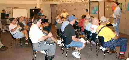 Collier Library, Houston Texas, 1:00 p.m., August
14, 2004, Chuck West, President, presiding. 38 members were present with
two Guests, Clyde Crouch and Norm Berls.
Collier Library, Houston Texas, 1:00 p.m., August
14, 2004, Chuck West, President, presiding. 38 members were present with
two Guests, Clyde Crouch and Norm Berls.
Business Meeting
Minutes are sent via email or regular mail to club members.
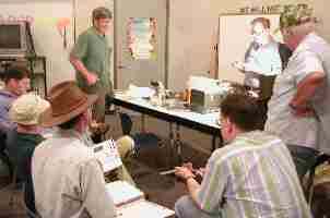
Presentation
 Don
Foster discussed the merits and pitfalls of the various paths through the patent
process. He talked about what kinds of people to seek help from in evaluating
ideas and identifying alternative forms the ideas might take. He also discussed
non-disclosure agreements and his use of witnessed engineering logs to determine
priority. Don related his experiences during his engineering career, Examples
were given of applicable and non-applicable ideas/patents developed during engineering
activities and how that might affect ownership of patents.
Don
Foster discussed the merits and pitfalls of the various paths through the patent
process. He talked about what kinds of people to seek help from in evaluating
ideas and identifying alternative forms the ideas might take. He also discussed
non-disclosure agreements and his use of witnessed engineering logs to determine
priority. Don related his experiences during his engineering career, Examples
were given of applicable and non-applicable ideas/patents developed during engineering
activities and how that might affect ownership of patents.
Special Interest Groups Activity:
Novice Group
 The
novice group reviewed Rich Pichler's minimum machinist's tool boxes as listed
in HMSC Aug 2003. We discussed the merits of various measuring tools.With
a calibrated stereomicroscope, we reviewed the scribe marks on a Dykem'd (layout
dye) blank. The scribe mark of a new General Tool No. 84 scriber was found to be about 4-5
thousandths wide which limits the accuracy of a -precision layout. It was
suggested to use razor blade for scribing, an "x-acto" blade, or a surgical blade. We will check them out at
the October meeting
The
novice group reviewed Rich Pichler's minimum machinist's tool boxes as listed
in HMSC Aug 2003. We discussed the merits of various measuring tools.With
a calibrated stereomicroscope, we reviewed the scribe marks on a Dykem'd (layout
dye) blank. The scribe mark of a new General Tool No. 84 scriber was found to be about 4-5
thousandths wide which limits the accuracy of a -precision layout. It was
suggested to use razor blade for scribing, an "x-acto" blade, or a surgical blade. We will check them out at
the October meeting
One "Machine Tool Practice" notebook was given to a new novice.
Future plans for Sept 11, 2004 include "broaching" by Dennis Cranston and for October 9, 2004 include "tapping and die threading" by Rich Pichler, and others. - by Rich Pichler
Foundry Group
|
||||||||
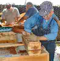
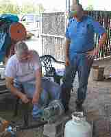
The Foundry sig met at Zube Park, Houston, Texas on July 18, 2004
to get the club furnaces up and running. Since there was sand, patterns, idle
hands and another furnace present, we also busied ourselves with ramming up some
molds for some switching frogs we have committed to pouring for the Houston
Area Live Steamers, HALS. The
first pour was made with Ray Ethridge's turkey fryer furnace.
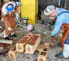
Ed Gladkowski, Tom Moore
and Dennis Cranston got one of the club furnaces going and we made two pours with it. The furnace melted aluminum very
quickly. We poured until the sand got too hot to
handle! by Ray Etrridge
CNC Group
The group discussed power supplies for servo/stepper motors and Larry Hill's recent acquisition of a "TAIG" CNC ready vertical mill.
Show and Tell
|
|
|
Joe Yeiser showed a shop-built bench top drill press. |
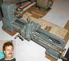
Jean Hart showed his cleaned up bench lathe that he acquired at the recent club swap meet. |
|
|
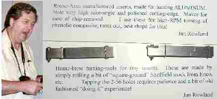
Jan Rowland showed some small inserts for contour turning aluminum and their holders. See arlicle below. He also showed a magazine Cutting Tool Engineering. |
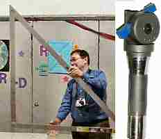
Dick Kostelnicek showed an enormous folding square and an adjustable angle fly cutter with an R-8 shank patterened after a recent article in Home Shop Machinist. |
Joseph Scott showed a fixture for holding a bolt stop (for a Johnson machine gun) during the various machining operations. He is also looking for a source of 6150 steel in plate form. |
Emmet Carstens mentioned a catalog for Cy-Fair college and classes available. (No picture)
Featured Articles
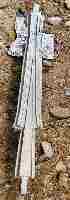
Application Specific Home-Brew Turning Tool Holders for Stock Inserts
by Jan Rowland - HMSC Member
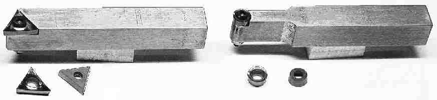
|
Shown above are home-brew turning-tools for tiny inserts. They are made by simply milling bits of �square-ground� Sheffield stock from Enco or others. Tapping the 2-56 holes requires patience and a bit of old fashioned experience! The 6-mm. round, and 6-mm. triangular IC inserts are from Rouse-Arno. These have the very high rake-angle and polished cutting-edge specifically for cutting aluminum. This makes for efficient chip removal for that material. I use these for high RPM turning of phenolic composite and exotic hardwoods. Fortunately, this aluminum-cutting design seems ideal for my application! |
Just glancing through catalogs and internet sites of insert vendors, one realizes there are surely hundreds of insert-types and shapes available. Lucky for me, I discovered the ideal ones for my application.
I turn pipe organ drawknobs of �exotics� such as rosewoods and ebonies, and from phenolic-impregnated wood composite known by the manufacturer�s name, �Dymondwood�. This latter stuff is wonderfully consistent to turn, but it is somehow abrasive and slightly corrosive when it is hot and spraying apart during turning. Thus, HSS tooling will last for fewer than 100 pieces before becoming too dull to continue. This would, of course, indicate carbide should be used. When I first began this kind of work in the late 70�s, I simply selected the �next-nearest-to-ideal� brazed-carbide turning tools from Enco, etal., and ground an initial very sharp edge, even sometimes shaping them for the particular job, with a diamond-grit wheel before beginning the hardwood turning. This might have been a reasonable edge for mild steel, but there was still zero rake, and the Pacific Rim carbide seemed to need touch-up sharpening more rapidly than I imagined it should.
Replaceable inserts came to mind now and then, but this operation required such a small lathe-tool that I initially rarely imagined inserts so small were avaliable. Guess it was an ad in M.A.N. magazine or the like for the tiny Rouse-Arno 6 mm. IC inserts that got me to thinking, and they offered individual samples, back then, to try �On your particular application�; so I let �em give me the samples. It turned out that those specifically made for aluminum turning have a very sharp positive rake angle, and are �ground on all sides�, and are actually mirror finish on top, so they turned out ideal for the composite and exotic hardwood turning.
No, they do not give �em away! The 6 mm. round inserts are about $3.80 each in ten-packs, and the 6 mm. IC triangle inserts are about $7.60, last time I ordered. There is a U.S. office for the firm, so ordering is no particular hassle except that sometimes they have to wait for delivery from the factory in Germany, and that can take longer than the U.S. Government�s bureaucracy, sometimes. They are also available TiN coated for a couple bucks extra per insert, but I fortunately have no need for that in this application. The round ones can be turned 180�, sometimes even just 120�, for a fresh edge, so these will sometimes last through 400 drawknobs. The triangles can be turned three times if one is careful, and those will do the usual �right-hand turning� for as many parts. Thus, the insert-cost is acceptable.
The insert-holders shown here are totally home-brew, made from standard 3/8� square-ground Sheffield stock. That sold by Enco is just fine for this application. Interesting how �doing it!� can teach an ol� dummy the way things work: 1018 CR �mild steel� is a bit mild for this application, I have found. The handling, use, and insert-changing makes such holders quite a mess after a dozen jobs, but the Sheffield stuff, being tougher, though not hardened, lasts just fine. These have an interestingly-countersunk screw-hole which will take a standard U.S. hex-socket cap-screw and center the insert, as tightened. I tap the steel, and use a #2 hex lock-nut below that, as you can barely see in the photos.
Static Balancing of Grinding
Wheels
by Dick Kostelnicek - HMSC Member
|
|
|
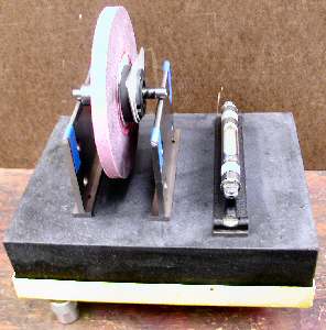
 You
can statically balance vitrified grinding wheels for both your surface and pedestal
grinders with a few common shop tools. Don't worry about dynamic balancing.
These wheels don't need it since they are large in diameter compared
to the axial thickness and they don't change shape when turning at rated
speed. First, build two arbor supports from pieces of ground parallels,
as shown in the photo at the left. I place a very small drop of super glue on
each end of a parallel as I stack them on top of one another. Later, you can
disassemble them by breaking the glue bond and cleaning the residue with
acetone, an excellent solvent for cyanoacrylate glue. Use masking tape (colored
blue in the photo}
to secure the drill rod to the top of each stack. The round drill rods prevent the
sharpness of the edges on the parallels from interfering with the free
wheeling of the wheel arbor. Also, debris will be easily squeezed
out from under the arbor while rolling on a round rather than a flat surface. Make
sure the surface plate is perfectly level in both directions. My plate is supported
in a metal frame that has three adjustable screw feet, making it
easy to level.
You
can statically balance vitrified grinding wheels for both your surface and pedestal
grinders with a few common shop tools. Don't worry about dynamic balancing.
These wheels don't need it since they are large in diameter compared
to the axial thickness and they don't change shape when turning at rated
speed. First, build two arbor supports from pieces of ground parallels,
as shown in the photo at the left. I place a very small drop of super glue on
each end of a parallel as I stack them on top of one another. Later, you can
disassemble them by breaking the glue bond and cleaning the residue with
acetone, an excellent solvent for cyanoacrylate glue. Use masking tape (colored
blue in the photo}
to secure the drill rod to the top of each stack. The round drill rods prevent the
sharpness of the edges on the parallels from interfering with the free
wheeling of the wheel arbor. Also, debris will be easily squeezed
out from under the arbor while rolling on a round rather than a flat surface. Make
sure the surface plate is perfectly level in both directions. My plate is supported
in a metal frame that has three adjustable screw feet, making it
easy to level.
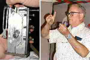
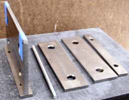
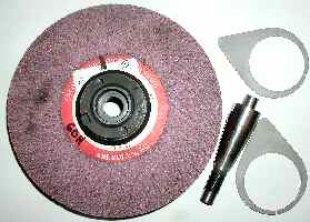
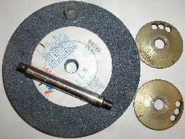
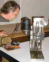
 Surface
Grinding Wheels First, dress the wheel while mounted on the
machine for which it is to be used. This will guarantee that it is round,
a necessary step for new, inexpensive, or damaged wheels. Then,
mount it on a dummy tapered arbor (see above right photo). For balancers, I
use a pair of thin spring shims. They are made from 1/8-in. aliminum sheet, split at the bottom of the large hole,
and clamp over the wheel hub.
Surface
Grinding Wheels First, dress the wheel while mounted on the
machine for which it is to be used. This will guarantee that it is round,
a necessary step for new, inexpensive, or damaged wheels. Then,
mount it on a dummy tapered arbor (see above right photo). For balancers, I
use a pair of thin spring shims. They are made from 1/8-in. aliminum sheet, split at the bottom of the large hole,
and clamp over the wheel hub.
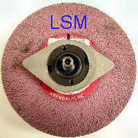
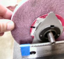
Now, place the wheel arbor on the two supports and allow it to settle to its heavy point (without shims). Mark the high spot of the wheel, calling it the light side mark or LSM, on the edge of the round paper blotter. Then, mount the two shims with their projections perpendicular to the LSM as seen in the above left photo. Rotate both shims in opposite directions a few degrees toward the LSM. Roll the wheel so that the LSM is parallel to the surface plate, and let it settle to its heavy side, right photo. If the LSM is still on top, move both shims closer to the LSM until the wheel will not rotate when the LSM is turned parallel to the surface plate. Some times you may not rotate both shims by the exact same amount in opposite directions. Then the LSM may not be at the top or bottom after the wheel settles. In that case, move just one of the shims to reset the LSM vertical. This will take some practice, as you will always choose the wrong shim to move or move it in the wrong direction. When the wheel stops rotating at an arbitrary point, well almost any point because you have to stop when it is good enough, then you are done, as seen in the lower left photo..
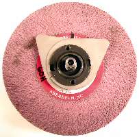
 Pedestal
Grinding wheels The photo at the right shows an 8-in. pedestal
grinding wheel to be balanced. I use a lathe mandrel having a very slight
tapered, but that is of no consequence here, to support the wheel and its metal
wheel flanges during balancing. I've lightened up one side of each flange by
drilling a few holes near the edge. Now the side without holes is the heavy
side of the flange and plays the same role as the weighty projection of the
clamp-on flanges discussed above in reference to surface grinding wheels. Here,
however, you must place one flange on each side of the wheel. Just as discussed
above, start without flanges to determine and mark the light side or LSM of the
wheel. Place the flanges against opposite sides of the wheel so that the lightening
holes are along a line parallel to the surface plate and facing toward opposite
sides of the wheel. Now proceed to counter rotate both flanges so the lightening holes
move away and downward from the LSM. Stop when the wheel settles at an arbitrary point.
Pedestal
Grinding wheels The photo at the right shows an 8-in. pedestal
grinding wheel to be balanced. I use a lathe mandrel having a very slight
tapered, but that is of no consequence here, to support the wheel and its metal
wheel flanges during balancing. I've lightened up one side of each flange by
drilling a few holes near the edge. Now the side without holes is the heavy
side of the flange and plays the same role as the weighty projection of the
clamp-on flanges discussed above in reference to surface grinding wheels. Here,
however, you must place one flange on each side of the wheel. Just as discussed
above, start without flanges to determine and mark the light side or LSM of the
wheel. Place the flanges against opposite sides of the wheel so that the lightening
holes are along a line parallel to the surface plate and facing toward opposite
sides of the wheel. Now proceed to counter rotate both flanges so the lightening holes
move away and downward from the LSM. Stop when the wheel settles at an arbitrary point.
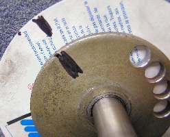
 Witness mark
the
flange against the LSM on each side of the wheel as seen in the photo at the
left. Finally mount the wheel and its flanges on the machine's arbor and
spin it up to speed for a test run.
Witness mark
the
flange against the LSM on each side of the wheel as seen in the photo at the
left. Finally mount the wheel and its flanges on the machine's arbor and
spin it up to speed for a test run.
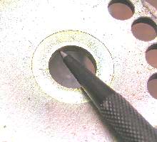
Now, as will often happen, the wheel flanges will not be snug on the dummy arbor during balancing. They may try to always settle to their heavy side while you are rotating the wheel. You may not notice the slippage of the flange as the wheel is rocking to and fro. This can lead to great frustration. Solve this problem by putting a bit of chewing gum between the flange and the wheel. Or better yet, upset the inside of the flange arbor holes with a prick punch as seen in the right hand photo. Either of these two methods will provide enough friction and prevent the flange from rotating relative to the grinding wheel on its own.
I hope your wheels run with reduced vibration. You may even see less waviness on the surface finish of the items produced on your surface grinder.
|
Visit Our Home Page at |
 |
Right click below then select [Save
Target As...]
From Netscape select [Save Link As..]
Microsoft
Word version of this newsletter 602 KB


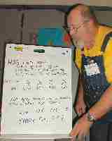 Doug Chartier presented a situation that he had run into concerning
calculation of milling machine speeds and feeds for 304 stainless
steel. The large range of solutions arrived at from various recommendations
and references were shown via visual aids. He also asked that everyone
bring their Machinery's Handbook next month.
Doug Chartier presented a situation that he had run into concerning
calculation of milling machine speeds and feeds for 304 stainless
steel. The large range of solutions arrived at from various recommendations
and references were shown via visual aids. He also asked that everyone
bring their Machinery's Handbook next month. Richard Pilcher passed around pictures and descriptions
of various tapping tools. He also showed pictures of the
Chicago Museum of Science and Industry's model train setup.
Richard Pilcher passed around pictures and descriptions
of various tapping tools. He also showed pictures of the
Chicago Museum of Science and Industry's model train setup.