Building a
"Zero-It" Type Indicator Holder
Introduction
The design of this device is based on the "Zero-It"
holder made by Mitutoyo and others. The holder can be used with
any Test Indicator that has dovetails, or those that have a
.250" diameter top stud. The holder block could be easily
modified for use with indicators such as the Starrett "Last
Word" type, or dovetail adapters can be purchased for these
indicators.
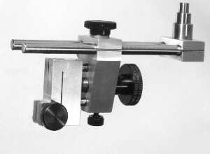
The supplied drawings differ from the photograph in only a few
places. The spindle in the prototype was much shorter. The screw
in the side of the Holder Block is smaller. Also, the main block
in the prototype was 5/8" thick, not 1/2" as in the
final version. Please check your kit to make sure all of the
materials in the list were supplied correctly.
Construction
Construction is not too difficult. There are only a couple of
areas where special attention is required. These are the holes
used for the rods for the course and fine adjust. This is because
even a small amount of misalignment can cause binding in the
mechanism. The instructions detail the use of a dial indicator
for locating the holes to be drilled. If you have a digital
readout, the dial indicator should not be necessary. All holes
should first be started with a center drill, this helps insure
that the hole will be started straight and in the correct
location.
Spindle Block
- Square-up and mill the block to size. 1.125" x
0.625" x 0.500 (ref)
- Clamp block in vise so that the 5/8 side is up.
- Locate the center of the side using your normal
procedure.
- Use an "F" drill bit and drill full diameter
.280" deep.
- Finish the hole using a #7 drill bit.
- Tap the hole 1/4-20.
- Remove the block from the vise and chamfer both the top
and bottom of the hole.
- Put the block back in the vice with the 1/2" side
facing up, 1.125 side aligned with the "X"
axis.
- Locate the center of the block as in #3 above.
- Fasten a dial indicator to the mill such that it can be
used to measure travel on the "X" axis.
- Preset the dial indicator to 0.500", this is the
center of movement.
- Move to the left 0.375" for the first hole. Lock
down the table.
- Center drill, then drill through 15/64"
- 14. Ream the hole to .250" or use a 1/4" drill
bit and carefully drill the hole to size.
- Unlock the table, move right until the indicator reads
0.375" on the other side of center. Lock the table.
- Repeat steps 13 and 14 above.
- Remove the piece and chamfer both ends of the two holes.
- Cut the slot using a bandsaw or hacksaw.
Main Block
- Square-up and mill the block to size. 1.750" x
1.125" x 0.500(ref)
- Clamp the block in the milling vise such that the 1.75 x
1.125 side is facing up, and that the 1.75" side is
aligned with the "X" axis.
- Locate the center of the block in the "Y" axis
(center of the 1.125 dimension), and lock the
"Y" axis.
- Locate the top edge (left hand edge) of the block and
zero the dials on the handwheels. Move to the right
1.125", this is the location of the hole marked
"C". Lock down the table.
- Center drill, then drill through with an "F"
size drill.
- Mount a dial indicator as before with the Spindle Block.
- Unlock the table and move 0.400" to the left. Lock
the table.
- Center drill then drill through with a 11/64" drill
bit.
- Ream the hole to .1875, or use a 3/16 drill bit.
- Check the size of the hole by sliding one of the pieces
of 3/16 drill supplied. It should slide through the hole
without much effort. If it if too tight, try another pass
with the same drill bit, or try another bit.
- Unlock the table, Move to 0.400" on the other side.
Lock the table.
- Repeat steps 8, 9, and 10 above.
- Remove the indicator, unlock the table, and move to
0.250" from the top (left side). Lock the
"X" axis.
- Mount a dial indicator such that movement on the
"Y" axis can be measured.
- Using the "Y" axis, locate and drill the two
0.250" holes in a similar manner as with the Spindle
Block.
- Remove the piece from the vise. Chamfer all holes.
- Mount the piece back in the vise with 1.125 x .5"
side nearest the two .250" holes (the top side), up.
- Locate the center of this side and drill and tap as in 4,
5, and 6 of the Spindle Block. Drill the #7 hole full
diameter to .700"
- Turn the block over in the vise and drill and tap the
6-32 hole for the Fine Adjust Lock Screw.
- Remove the block from the vise and by using magic marker
on Dykem bluing, scribe the lines for the angles to be
cut on the sides of the main block.
- Clamp the block in the vise with one of the cut lines
lined up with the top of a thin parallel placed on top of
the vise jaws.
- Mill off the excess material.
- Do the other side of the block as in 21 and 22 above.
- Knock off any burrs and break sharp corners with a file.
Holder Block
- As in the parts before, square-up and mill the block to
size. 1.500" x 0.975" x 0.500(ref)
- Mark the front of the block, (where the dovetail will be)
with a magic marker.
- Set the block in the milling vise with the 0.975 x
0.500" end to the top. Make sure the block is
sitting square to the vise.
- Locate (0.475" from the side with the mark) and
drill the 1/4" hole through the block from top to
bottom.
- Remove the block from the vise and chamfer both ends of
the hole.
- Place the block back in the vise with the front side (the
side with the mark) down. The long dimension
(1.500") should be aligned with the "X"
axis.
- Find the center of the block on the .500 dimension
("Y" axis). Lock the "Y" axis.
- Locate the top ( left ) edge of the block and move to the
right 0.600". This is th center of the hole marked
"G". Lock the table.
- Mount a dial indicator on the "X" axis as
before. Preset the indicator to 0.500.
- Drill a hole 1/2" deep with a "Q" drill
bit. This will break through into the 1/4" hole,
this is OK. Tap the hole with a 3/8-24 tap. Finish with a
bottom tap if you have one.
- Drill the two 3/16 holes as you did in the Main Block.
Drill until the holes break through into the 1/4"
hole.
- Remove the block and chamfer the holes.
- Place the block on it's side in the vise. Drill and tap
the hole marked "D". Drill with the larger bit
first then through with the tap size bit. Just as done
previously.
- Remove the block from the vise and set it back in with
the marked side up. Make sure at least 1/4" of the
block is above the vise jaws.
- Mill out the 0.225 x 0.975 area above the dovetail.
- Using a 3/16" end mill, cut a slot 0200" wide
by 0.070" deep. For roughing the dovetail.
- Use a small triangular file that has been safed on one
side to cut the 60° angle on each side of the dovetail.
Keep the file flat on the bottom of the groove. Test the
fit of the dovetail to your Test Indicator to make sure
it fits snugly yet smoothly.
- Cut the two slots using a 0.020" slotting saw or a
hobby razor saw. The slot in the front has to be cut all
the way from top to bottom. The height of the slot on the
side is not critical, be sure to material at the top to
act as a spring.
Spindle
- Mount the 1/2" by 1.875" piece of CRS in the
lathe chuck with 1" protruding from the chuck.
- Face the end of the workpiece.
- Turn the .375" and the .250" diameters shown on
the drawing.
- Cut a slight 45° chamfer end and the two shoulders that
were created.
- Remove the workpiece from the chuck and make a scribe
mark on the workpiece 0.500" below the .375"
portion.
- Place the piece back in the chuck with the unturned
portion sticking out. Make sure the scribe mark is
outside of the chuck by at least 1/16".
- Turn to 0.250" up to the scribe mark.
- Turn to 0.246" up to about 0.174 from the shoulder.
This will be the threaded portion of the spindle.
- Cut a 1/4-20 thread on the spindle shaft. Use the Spindle
Block as a thread depth gauge.
- Trim the spindle to length and chamfer the end of the
thread with the 60° threading tool.
- By chucking on the 3/8" diameter. It is possible to
clean-up the 1/2" diameter using a cutting tool or a
file.
Fine Adjust Screw
- Mount the 1/2" x 2.5" piece of CRS in the lathe
chuck and face the end square and clean.
- Drill a small center hole if you plan to use the
tailstock while turning this piece.
- Extend the piece out of the chuck so that at least
1.75" is protruding from the chuck.
- Make sure the piece is running as true as possible, tap
with a hammer if necessary while tightening the chuck.
- Carefully cut the diameter to 0.375" - 0.372"
up to the chuck jaws.
- Turn the 0.250 diameter portion of the screw.
- Cut the threads at 24 TPI as close to the chuck as you
safely can. Use the included 3/8-24 nut as a thread
gauge.
- When the thread is finished, chamfer the right end of the
thread with the threading tool.
- Either cut off the piece in the lathe or remove the piece
and cutoff with a hacksaw in a bench vise (make sure you
grip the waste side with the bench vise).
- Place the piece back in the lathe by chucking on the
1/4" diameter end.
- Dress the cutoff end to length and chamfer the threads.
- Do not drill the 1/16 hole yet, that will be done at
final assembly.
Knob
- Chuck the 1" x 1.5" piece of CRS in the chuck
so that at least 3/4 to 7/8" is protruding.
- Face the end and drill the 1/4" hole 0.375"
deep.
- Turn the 0.500 diameter portion.
- Clean-up the 1" diameter so that it is bright and
smooth.
- Using a medium knurling tool, cut a knurl at least
0.2" wide.
- Using the thread cutting tool, chamfer the shoulder on
the threaded portion and the knurled portion.
- Cut off the part either on the lathe or at the bench.
- Place the piece back in the lathe chucking on the
1/2" diameter.
- 9. Face the cutoff side and cut a chamfer on the knurled
shoulder.
- Do not drill the 1/16" hole at this time.
Final Assembly
- Make sure all parts are clean and deburred. Graining the
aluminum parts using a 180 grit belt on the sander makes
a nice finish. Use WD-40 to prevent the belt from
"burning" the aluminum. It should come out
bright and shiny. The knob on the prototype was blued by
degreasing the part and heating it carefully with a
propane torch until the desired color was reached.
- Put the Fine Adjust Screw through the hole in the Main
Block. Place one or two paper washers on the 1/4"
shaft of the screw before pushing the Knob in place. The
paper will provide a small amount of clearance after the
knob is fixed in place. Push the knob on and clamp the
assembly in the milling vise so that the knob is pressed
tightly in place. Drill the 1/16" hole, and press in
the roll pin. Now remove the paper. The Fine Adjust Screw
should rotate smoothly.
- Face off and chamfer the ends of all four pieces of drill
rod that were supplied.
- Clean-up the 1/4" hole that goes from top to bottom
on the Holder Block with a hand held 1/4" drill bit.
Slide on of the 1/4" drill rods into the hole. Apply
a small amount of Loc-Tight to the inside of the
3/16" holes and to one end of each of the 3/16"
drill rods. Push the two 3/16" rods into the holes.
Clean off the excess Loc-Tight from the outside of the
holes and rods. Push the Main Block over the pins and
screw the fine adjust so the the Main Block is about
1/4" from the Holder Block. Remove the 1/4"
drill rod from the hole in the Holder Block and set the
assembly aside for the Loc-Tight to dry.
- Screw the Spindle lightly into the Spindle Block. Push
the two 1/4" drill rods into the block until the
ends are flush with the block. The best way to tighten
the spindle without marring it is to lock the spindle in
a collet and turn the assembly until it is tight enough.
- Press the Shear-Loc knobs on the socket head screws by
holding the screws lightly in a drill chuck (on a drill
press on tailstock of the lathe), placing the knob on the
screw, then pressing the knob on using the force of the
quill or tailstock.
- Using the 1/4" washer supplied, screw the 1/4"
screw into the top of the Main Block.
- Screw the 6-32 screw into the bottom of the main block.
- Using the supplied #8 washer, screw the 8-32 screw into
the side of the holder.
- Slide the Main Block and Holder assembly onto the Main
Rods and you are finished.
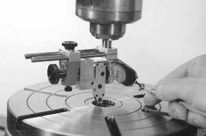
Aligning a rotary table
Appendix A
To build this project you should make sure you have access to
the following:
- Tap sizes #6-32, #8-32, 1/4-20, 3/8-24
- Drill bit sizes 1/16, #36, #29, 11/64, 3/16, #7, 15/64,
1/4, #F, and #Q
- Center drills #1 and #2
- Counter sink for chamfering.
- End mills 1/2" for general milling, 3/16 for cutting
slot for dovetail.
- Reamers of 3/16" and 1/4" would be helpful but
are not necessary.
- Small triangular file with one side safe.
- Test Indicator you wish to use for fitting dovetail.
- Dial Indicator with at least 1" of travel.
- Lathe
- Milling machine or milling attachment for lathe.
Appendix B
This is the list of materials supplied with the kit:
Quantity  Size                Material       Used in this part
  1      1.25 x 1.875 x 0.5   6061 Alum.     Main Block
  1      1.25 x 0.75 x 0.5    6061 Alum.     Holder Block
  1      1 x 1.625 x 0.5      6061 Alum.     Spindle Block
  1      1" dia. x 1.5        12L14 CRS      Knob
  1      0.5" dia. x 1.875    12L14 CRS      Spindle
  1      0.5" dia. x 2.5      12L14 CRS      Fine adjust screw
  2      0.188 x 1.375        Drill Rod      Fine adjust rods
  2      0.250 x 3.875        Drill Rod      Main rods
  1      8-32 x 1/2           SHCS*          Indicator dovetail lock
  1     #8 Shear-Loc Knob                    Indicator dovetail lock
  1      #8 Washer            Stainless      Indicator dovetail lock
  1      6-32 x 1/4           SHCS*          Fine adjust lock
  1     #6 Shear-Loc Knob                    Fine adjust lock
  1      1/4-20 x 1/2         SHCS*          Course adjust lock
  1     1/4 Shear-Loc Knob                   Course adjust lock
  1      1/4" Washer          Stainless      Course adjust lock
  1     1/16 x 3/8 Roll Pin   Steel          Knob Retainer
  1      3/8-24 nut           Steel          Gauge for cutting
                                             fine feed screw

* Socket Head Cap Screw
Appendix C
Download Adobe Acrobat
Version of drawing (43K)
